JUNCTEK
2.Introduction of the measurement module
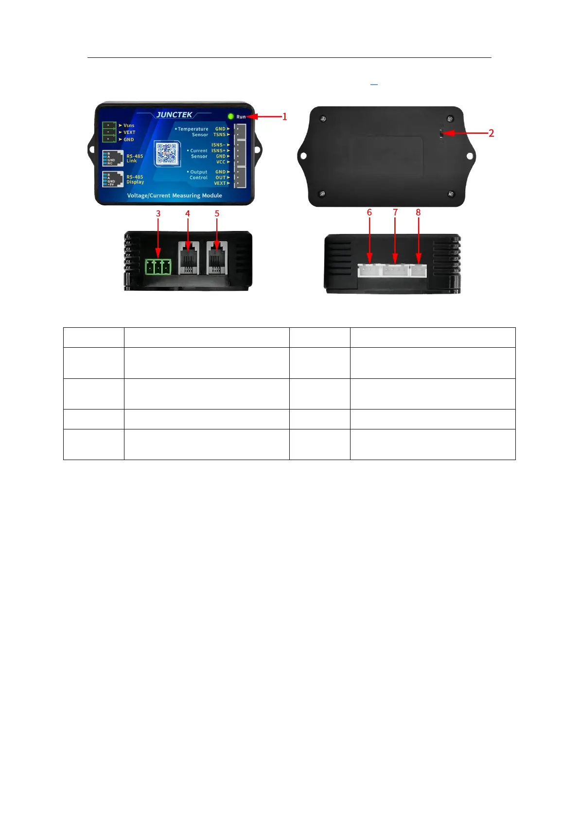
Figure 2-2-1 KH-F series measurement module diagram
Table 2-2-1 Instructions diagram of the KH-F series measurement module
485 communication
display interface
Relay output
control interface
485 communication
connection interface
External temperature
measurement interface
(1).Indicator light
The indicator light represents the working status. Slow flashing indicates
normal power supply and normal measurement.
(2).2-wire/3-wire power selection switch
The switch can be toggled to select external power or self-power. When the
switch is toggled up to 2W, it is suitable for self-power, and the voltage
measurement range is 10-120V. When the switch is toggled to 3W, it is
suitable for external power, and the external power voltage is 10-80V. For KH-F,
the voltage measurement range is 0-120V.
(3).Power interface
There are a total of three power interfaces, including the battery positive
interface (Vsns), the external power positive interface (VEXT), and the external
power negative interface (GND).
(4).RS-485 communication connection interface
Used for protocol communication, and can also be used to connect another
measurement module for multi-machine communication. From left to right,
they are: B, A, GND, NC.
 Loading...