Hangzhou Junce Instruments Co., Ltd.
Chapter 2 Meter Instruction
1. Measurement Module Introduction
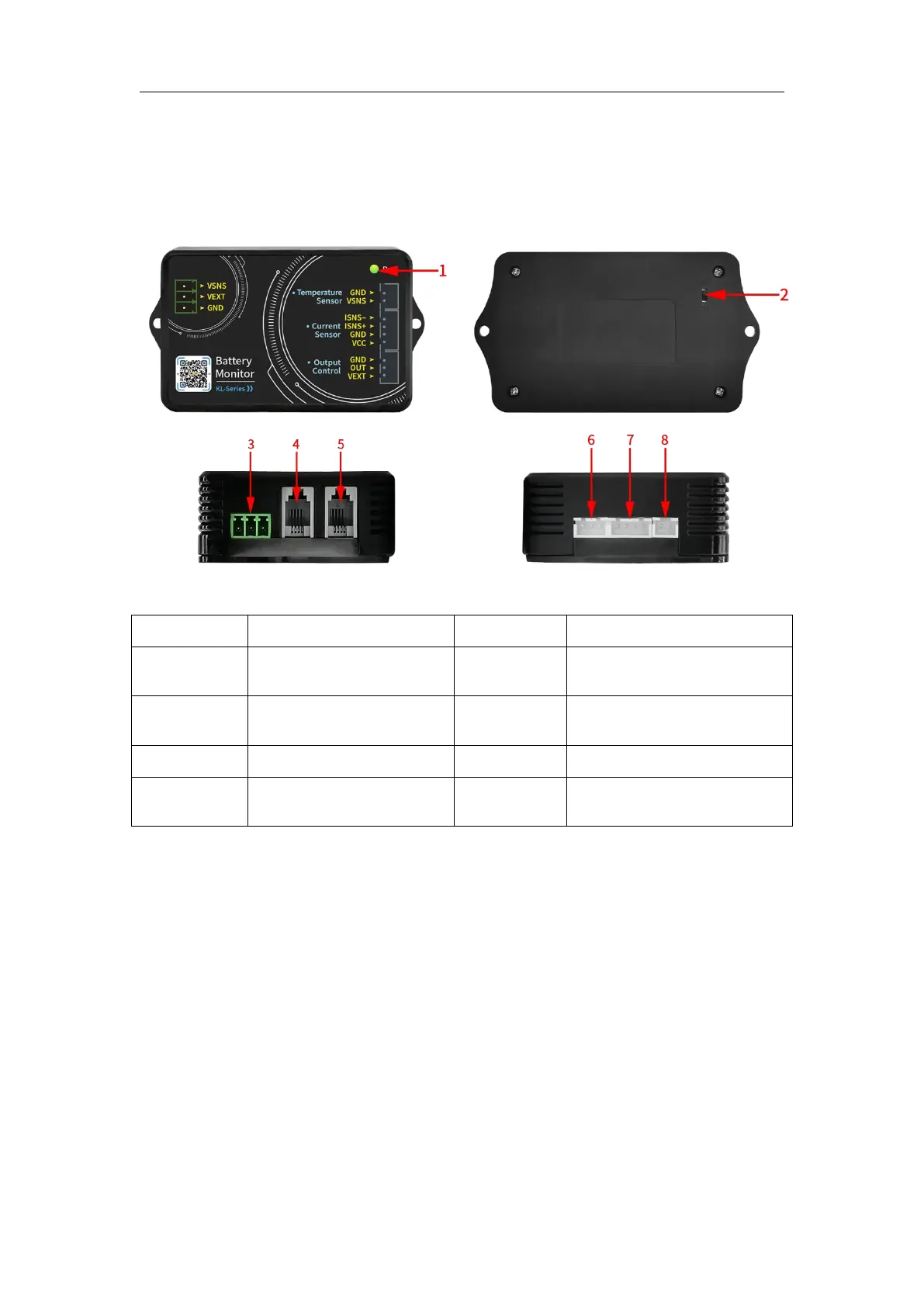
Figure 3-1-1 Schematic diagram of KL-F series measurement module
Table 3-1-1 KL-F series measurement module instructions
Display reserved
interface
2-wire, 3-wire power
supply selector switch
Relay output control
interface
485 communication
connection interface
External temperature
measurement interface
(1) Indicator light
The indicator light can be used to check the output status.
(2) 2-wire, 3-wire power supply selector switch
The toggle switch can be used to select external power supply or
self-powered. The switch to 2W is suitable for self-powered; the switch to 3W
is suitable for external power supply.
(3) Power supply interface
There are three power supply interfaces, battery positive interface: Vsns,
external power supply positive interface: VEXT, external power supply
negative interface: GND.
 Loading...