Hangzhou Junce Instruments Co., Ltd.
supply should not be connected wrongly or reversed.
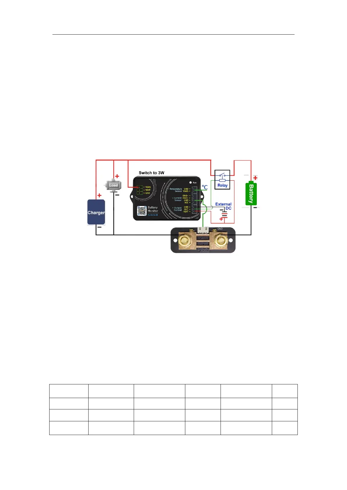
If you want to control the charging or discharging, you should connect the
wiring according to the wiring diagram of external power supply relay in figure
3-2-3. When the relay is closed, the indicator light will be on, and when it is
disconnected, it will be off as a prompt.
The negative pole of the battery is connected to the screw printed "BATT-"
on the Shunt. The negative pole of the charger and the negative pole of the
load are connected to the other screw of the sampler. It is better to use a
copper nose to connect it firmly. When charging, the current color on the
mobile phone APP is green, and the remaining capacity value increases.
When discharging, the current color is sky blue, and the remaining capacity
value decreases.
(The external power supply voltage is subject to the working voltage of
the relay; for example, 12V or 24V.
)
Figure 3-2-3 External power supply wiring diagram (Relay control)
3. Communication protocol control
We only provide communication protocol, customers can carry out
secondary development according to communication protocol.
(1) Summary
The command line is used as the control command, and the
communication rate is 115200. The PC sends out the command, the meter
parses and executes it, and then returns the result to the PC. The different
commands are described below.
The sending data format is as follows
:
 Loading...