Hangzhou Junce Instruments Co., Ltd.
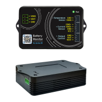
Figure 3-3-1 Self-powered wiring diagram
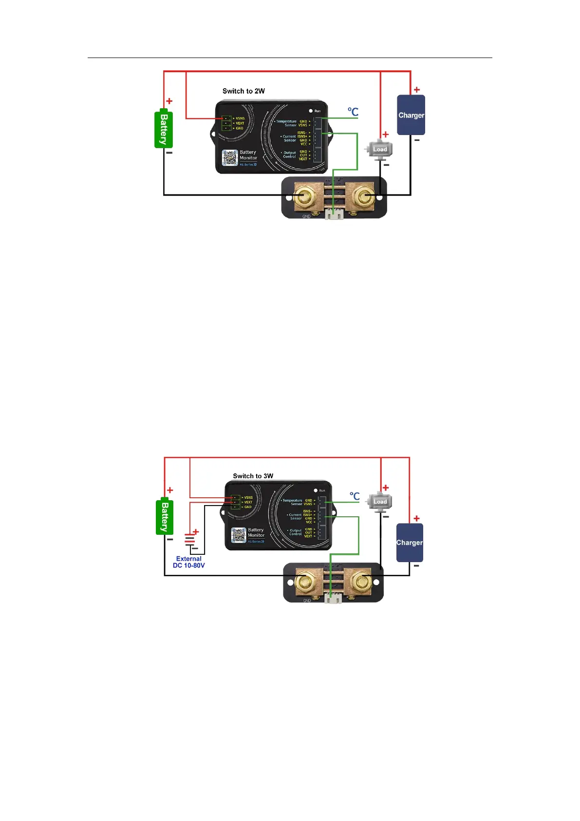
(2) External power supply wiring method
The measuring voltage range of the external power supply is 0-120V. First,
set the power selection interface switch to "3W", connect the positive pole of
the external power supply to the power interface "VEXT", and connect the
negative pole of the external power supply to "GND". When wiring, connect the
positive pole of the battery to the measurement interface "VSNS" in the power
interface. Note that the positive and negative poles of the battery and the
external power supply should not be connected incorrectly or reversed.
The negative pole of the battery is connected to the screw printed "BATT-"
on the Shunt, and the negative pole of the charger and the negative pole of the
load are connected to the other screw of the Shunt together. It is better to use
copper nose to connect firmly. When charging, the current color on the mobile
phone APP is green, and the remaining capacity value increases. When
discharging, the current color is sky blue, and the remaining capacity value
decreases.
Figure 3-3-2 External power supply wiring diagram
(3) External power supply wiring method (Relay control)
The working power of the relay is provided by an external power supply. If
the relay is connected, an external power supply with the same working
voltage as the relay should be provided. Connect the control ports of the relay
to the "OUT" and "VEXT" of the measurement module Output Control, connect
the positive pole of the external power supply to the "VEXT" of the Output
Control, and the negative pole of the external power supply to the "GND". Note
that the positive and negative poles of the battery and the external power
 Loading...