Hangzhou Junce Instruments Co., Ltd.
(4) 485 communication connection interface
It is used to connect the supervisor computer interface, and also can
connect to another measurement module through this interface to realize
multi-meter communication. The internal order from left to right is: B, A, GND,
NC.
(5) Display reserved interface (if you need display module, please purchase
separately)
Connect with the display module. When the measurement module has
power supply, the communication interface is live. The internal order from left
to right is: B, A, GND, +5V.
(6) Relay output control interface
The relay output control interface can be used with relays. The internal
sequence from left to right is: GND, OUT, VEXT.
(7) Sampler interface
Connect with sampler to detect current. The internal sequence from left
to right is: VCC, GND, ISNS+, ISNS-.
(8) External temperature measurement interface
Connect with temperature sensor to measure external temperature. The
internal sequence from left to right is: TSNS, GND.
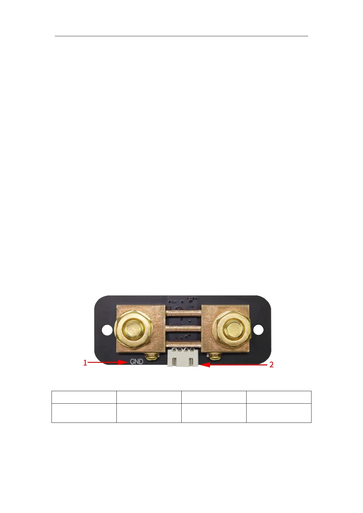
2. Sampler introduction
Figure 2-2-1 KL-F series sampler (100A sampler as an example)
Table 2-2-1 KL-F series sampler instructions (100A sampler as an example)
(1) Battery negative terminal
The negative terminal of the battery is connected to the screw with the
GND or BATT- mark.
 Loading...