Replacing Power Supplies 43
Chapter 3: Hardware and Servicing
2. Insert a 0V DC (positive voltage) return wire into the center COM connector and
a -48V DC power feed wire into either the left or right connector.
Figure 32: Wiring Power Feeds to the Terminal Block
3. Fasten the screws over the connectors.
4. Turn on the power switch.
To replace one of the DC power supplies:
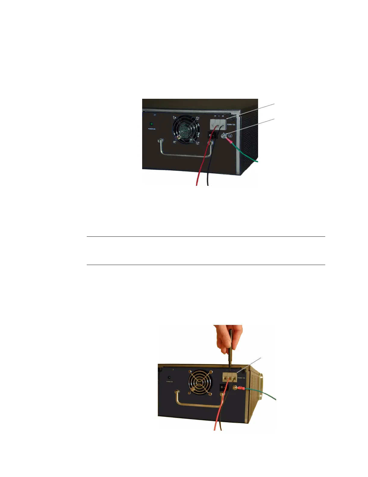
1. Loosen the retaining screws on the terminal block and remove the feed wires.
2. Loosen the hex nut on the grounding screw and remove the grounding wire.
Figure 33: Removing the Feed Wires and Grounding Wire
Positive
Voltage
WIre
Negative
Voltage
WIre
Grounding
WIre
Terminal Block
Grounding Screw
NOTE: If both power supplies are installed and either of them is off, the Alarm LED on the
front panel glows red. This warning indicates that maximum system reliability
requires all installed power supplies to be operational.
Loosen retaining screws
on the terminal block.
Grounding Wire
Feed Wires
Terminal Block