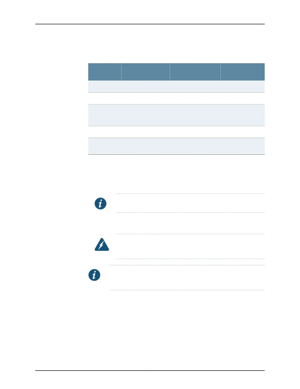
Table 4: Components to Remove from the Rear of a DC-PoweredMX2020
Router (continued)
Number of FRUsSlots
Component
Description
Component
No.
1–PSM air filter8
1PDM0/Input0DC PDM9
4–DC cable
manager–(standard or
extended)
10
1–Fan tray air filter11
2Fan tray 0 and fan tray 1
(behind access door)
Lower fan trays (two)12
To remove the components from the router:
1. Slide each component out of the chassis evenly so that it does not become stuck or
damaged.
2. Label each component as you remove it so you can reinstall it in the correct location.
NOTE: The MX2020 PSMs can be installed in any order in the chassis.
3. Immediately store each removed component in an electrostatic bag.
4. Do not stack removed components. Lay each one on a flat surface.
WARNING: Stacking components on top of one another can damage the
component parts.
NOTE: For complete instructions on removing router components, see the
MX2020 3D Universal Edge Router Hardware Guide.
To remove the upper and lower fan tray (see Figure 11 on page 22 and
Figure 12 on page 22):
1. Attach an electrostatic discharge (ESD) grounding strap to your bare wrist, and connect
the strap to an approved site ESD grounding point. See the instructions for your site.
2. Loosen the two captive screws on each side of the fan tray access panel and open.
3. Loosen the two captive screws on the fan tray faceplate.
21Copyright © 2015, Juniper Networks, Inc.
Remove Components