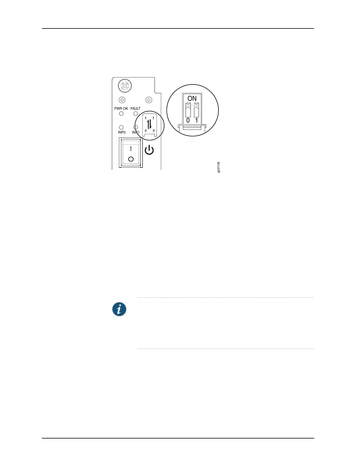
Figure 38: Selecting AC Power Subsystem Feed Redundancy
PWR OK
FAULT
INP0
INP1
10
ON
g007109
3. Ensure that the voltage across the AC power source cable leads is 0 V and that there
is no chance that the cable leads might become active during installation.
4. Using both hands, slide the PSM straight into the chassis until the PSM is fully seated
in the chassis slot. Tighten the two captive screws to secure the PSM to the chassis.
5. Verify that the INP0 or INP1 LEDs on the PSM are lit green steadily. The INP0 or INP1
LEDs are lit yellow if that input’s voltage is in reverse polarity. Check the polarity of
the power cables to fix the condition (see Figure 39 on page 57 and
Table 9 on page 57).
6. Attach an electrostatic discharge (ESD) grounding strap to your bare wrist, and connect
the strap to one of the ESD points on the chassis.
7. Move the switch to the on (|) position.
8. Verify that the PWR OK LED is lit green steadily. See Table 9 on page 57 for information
about MX2020 AC PSM LEDs.
NOTE: The MX2020 router configured for three-phase wye AC input power
must use only three-phase wye AC PDMs and AC PSMs. The MX2020
router configured for three-phase delta AC input power must use
three-phase delta AC PDMs and AC PSMs. AC and DC PSMs or PDMs must
not be mixed within a single router.
Copyright © 2015, Juniper Networks, Inc.56
MX2020 3D Universal Edge Router Quick Start