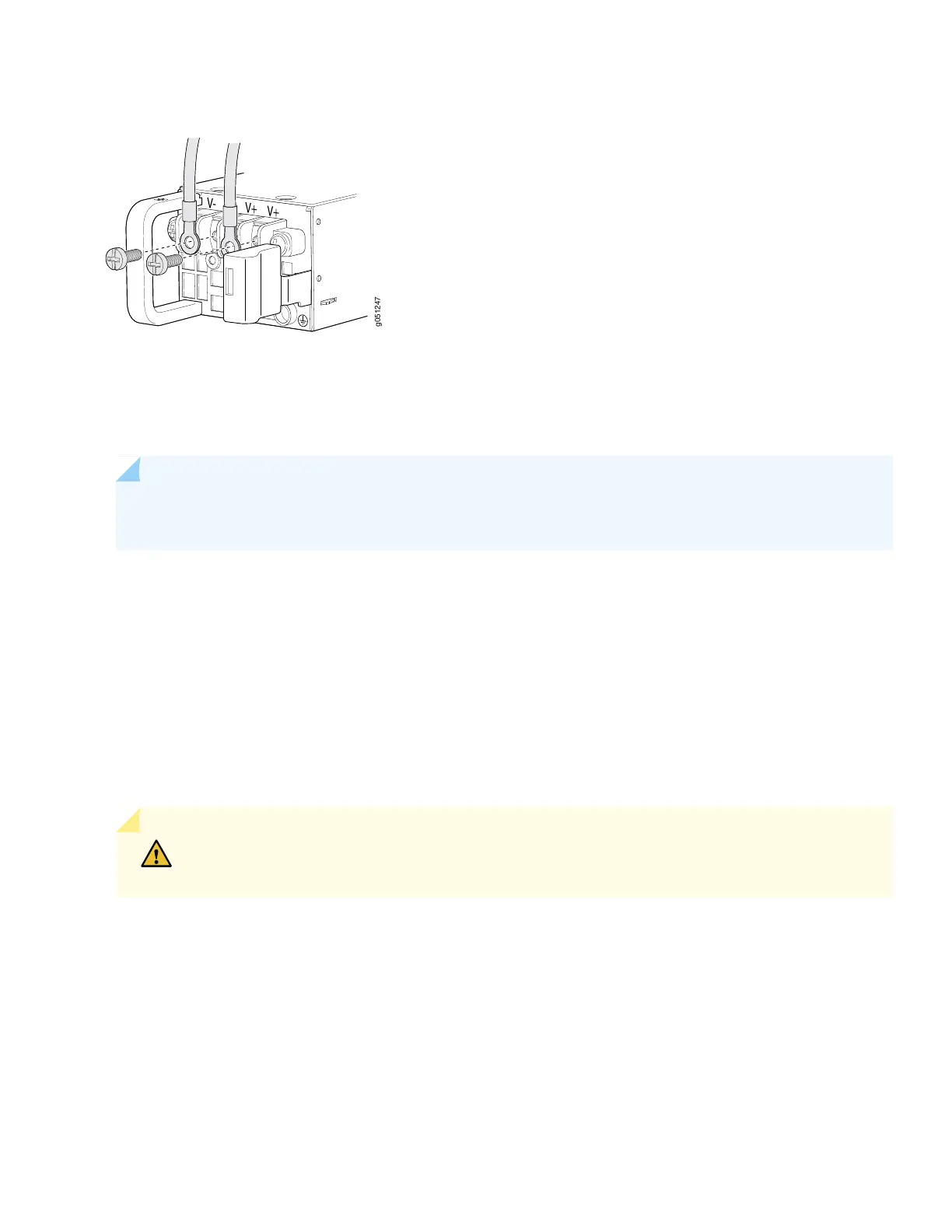
Figure 15: Secure Ring Lugs to the Terminals on the QFX51200-48Y or QFX51200-48T DC Power Supply
8. Replace the terminal block cover.
9. Close the input circuit breaker.
NOTE: The switch powers on as soon as power is provided to the power supply. There is no power switch
on the QFX5120.
10. If you are connecting the power supply in a QFX5120-48Y or QFX5120-48T switch, verify that the IN and OUT
LEDs on the power supply are lit green. If the fault LED (!) is lit, disconnect the power supply from the power source,
and replace the power supply (see Remove a Power Supply from a QFX5120 Switch).
•
•
If you are connecting the power supply in a QFX5120-32C switch, verify that the LED on the power supply is lit
green. If the LED is lit or blinking red, disconnect the power supply from the power source, and replace the power
supply (see Remove a Power Supply from a QFX5120 Switch).
Do not remove the power supply until you have a replacement power supply ready: you must install the power supplies
or a cover in the switch to ensure proper airflow.
CAUTION: Replace a failed power supply with a cover or a new power supply within one minute
of removal to prevent chassis overheating.
Step 5: Perform Initial Configuration
You must perform the initial configuration for QFX5120 switch by using the console port.
1. Verify that the switch is powered on.
2. Connect the console port to a laptop or PC.
16

 Loading...


