How to Set Up Your SRX320 Services Gateway
4
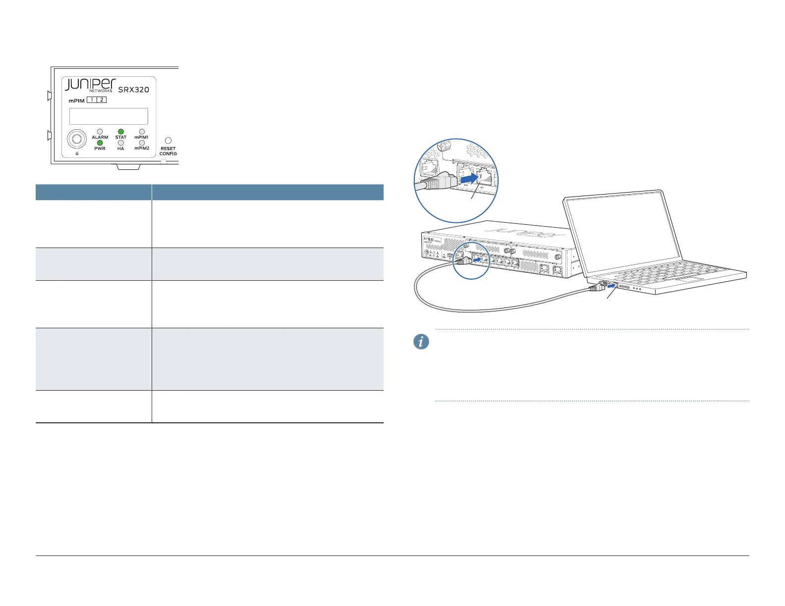
4. Note the following LED indications. Wait until the STATUS LED is solid green
before proceeding to the next step.
g000755
LED State
ALARM • Solid amber (noncritical alarm).
• Solid red (critical alarm).
• O (no alarms).
STAT • Solid green (operating normally).
• Solid red (error detected).
PWR • Solid green (receiving power).
• Solid red (power failure).
• O (no power).
HA • Solid green (all HA links are available).
• Solid amber (some HA links are unavailable).
• Solid red (HA links are not functional).
• O (HA is disabled).
mPIM1, mPIM2 • Green (mini-PIM is present and detected by the device).
• O (mini-PIM is not present or not detected by the device).
Configure the Device Using J-Web
To configure the device using J-Web, follow the steps in this section.
Connect the Management Device
1. To configure the device using J-Web (recommended), connect any of the
network ports numbered 0/1 through 0/5 to the Ethernet port on the
management device, using an RJ-45 cable.
7
Ethernet port
RJ-45 cable
Ethernet port
NOTE: The ge-0/0/0 interface (port 0/0) is a WAN interface. Do not
use this port for the initial configuration procedure.
If you will be using the Default setup mode to configure the device, use
only port 0/1. For information on the setup modes, see the following
Log in to J-Web section.
2. The services gateway functions as a DHCP server and automatically assigns
an IP address to the management device. Ensure that the management
device acquires an IP address on the 192.168.1.0/24 subnetwork from the
device.
If an IP address is not assigned to the management device, manually
configure an IP address in the 192.168.1.0/24 subnetwork. Do not assign
the 192.168.1.1 IP address to the management device, as this IP address is
assigned to the services gateway. By default, the DHCP server is enabled
on the L3 VLAN interface, irb.0 (interface ge-0/0/1 to ge-0/0/5). which is
configured with an IP address of 192.168.1.1/24.