6. Slide the Routing Engine or SCM into the slot until you feel resistance, and then press
its faceplate until it engages the connectors.
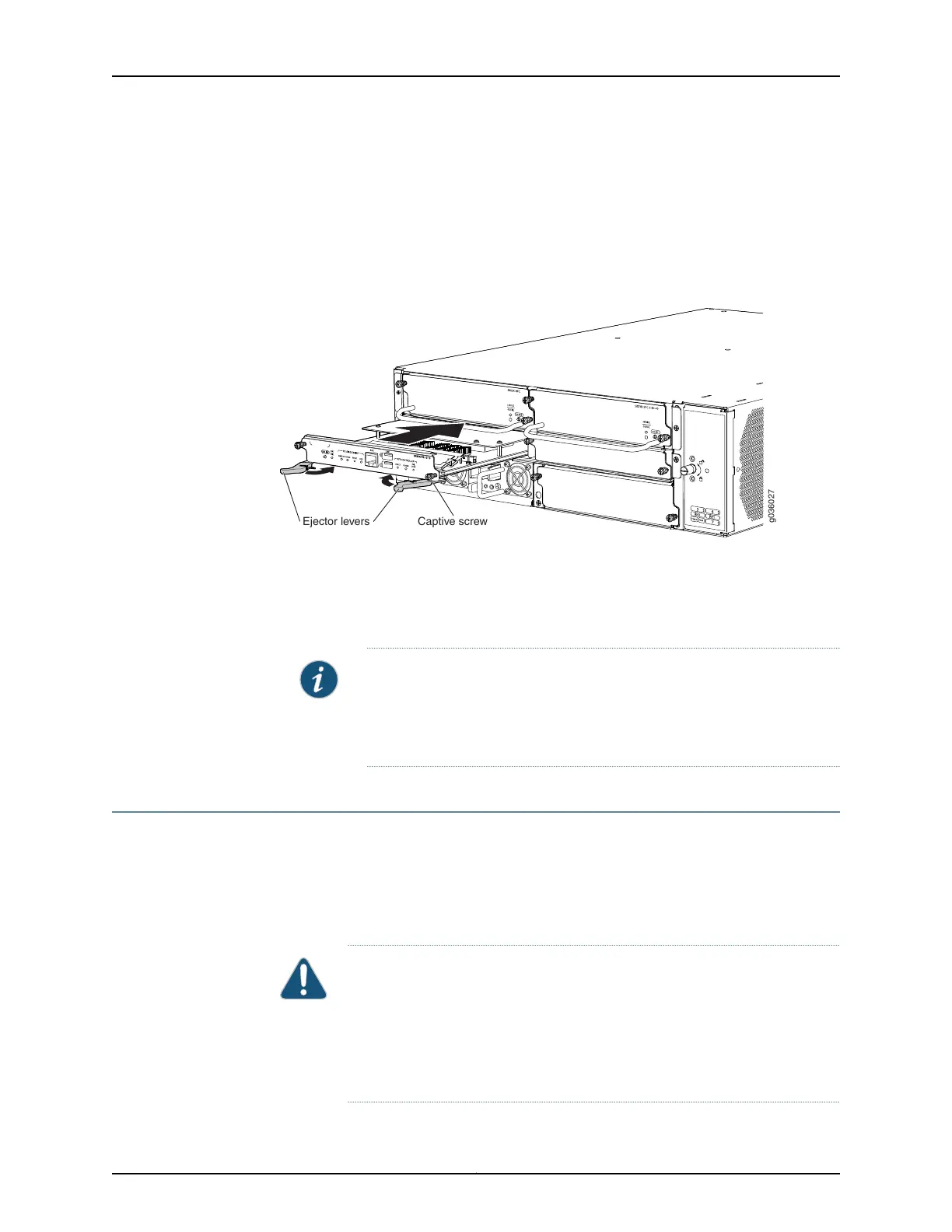
7. Press both of the ejector handles inward to seat the Routing Engine or SCM.
8. Tighten the captive screws on the left and right of the Routing Engine or SCM.
Figure 18: Installing a Routing Engine or SCM (SRX3400 Services Gateway
shown; SRX1400 and SRX3600 Similar)
g036027
Captive screwEjector levers
9. Reconnect cables previously attached to the AUX or USB ports.
10. Power on the services gateway by pressing the Power button on the front panel of
the SFB for three to five seconds. Wait for the services gateway to start. The OK/FAIL
LED on the Routing Engine or SCM faceplate should blink green, then light steadily.
NOTE: The Routing Engine might require several minutes to boot. If after
this time the OK/FAIL LED is red, remove and reinstall the Routing Engine.
If the OK/FAIL LED remains red, the Routing Engine is not functioning
properly. Contact your customer support representative.
Installing SFP, SFP+, and XFP Transceivers
Small form-factor pluggable (SFP), enhanced small form-factor pluggable (SFP+), and
10-Gigabit SFP (XFP) are transceivers that you install in sockets in various cards or
modules in the services gateway. These transceivers are hot-insertable and
hot-removable. Removing a transceiver does not interrupt the functioning of the card or
module, but the removed transceiver no longer receives or transmits data.
CAUTION: If you are having a problem running a Juniper Networks device
that is using a third-party optic or cable, the Juniper Networks Technical
Assistance Center (JTAC) can help you diagnose the source of the problem.
Your JTAC engineer might recommend that you check the third-party optic
or cable and potentially replace it with an equivalent Juniper Networks optic
or cable that is qualified for the device.
Copyright © 2016, Juniper Networks, Inc.24
SRX1400, SRX3400, and SRX3600 Services Gateway Module Guide