Juniper Networks SSG 520M and SSG 550M Security Policy
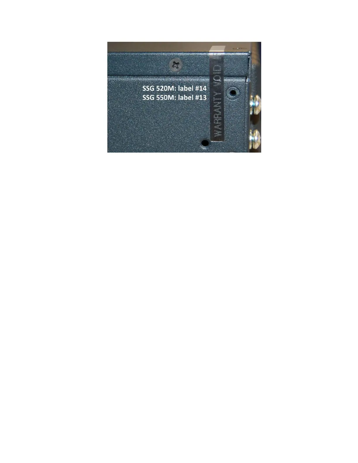
Figure 6: Rear corner of the SSG 520M and 550M
Tamper-evident seals (14 for the SSG 520M, 13 for the SSG 550M) should be applied to:
• The front of the device as shown in Figure 3:
• Label #1 applied vertically from the top of the chassis across the left edges of the slot
covers numbered 1 and 2.
• Label #2 applied vertically, overlapping with the last ¼ inch of label #1, covering the
slot covers numbered 2 and 3, extending on to the front of the chassis.
• Label #3 applied vertically from the top of the chassis across the right edges of the
slot covers numered 1 and 2.
• Label #4 applied vertically, overlapping with the last ¼ inch of label #3, covering the
slot covers numbered 2 and 3, extending on to the front of the chassis.
• Label #5 applied vertically from the top of the chassis across the left edges of the slot
covers numbered 4 and 5.
• Label #6 applied vertically, overlapping with the last ¼ inch of label #5, covering the
slot covers numbered 5 and 6, extending on to the front of the chassis.
• Label #7 applied vertically from the top of the chassis across the right edges of the
slot covers numered 4 and 5.
• Label #8 applied vertically, overlapping with the last ¼ inch of label #7, covering the
slot covers numbered 5 and 6, extending on to the front of the chassis.
• Label #9 applied horizontally from the left side of the chassis, extending toward the
center of the removable ventilation cover.
• Label #10 applied horizontally, extending across the right edge of the removable
ventilation cover and on to the front of the chassis.
• Label #11 applied horizontally to overlap labels numbered 9 and 10.
• The rear of the device:
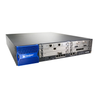
• For the SSG 520M, as shown in figure 4:
• Label #12 applied vertically from the top of the removable cover extending on to
the center of the power supply.
• Label #13 applied vertically across the screw to the left of the power supply fan.
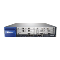
• For the SSG 550M, as shown in figure 5:
 Loading...