Rear Panel of WLC100 Wireless LAN Controllers
The rear panel of WLC100 controllers consists of the following components:
•
Earth ground connecting point
•
Slots for the screws used to secure the controller to the rack-mount tray by using
system lock brackets
•
Slot for the security cable latch
•
Power supply inlet
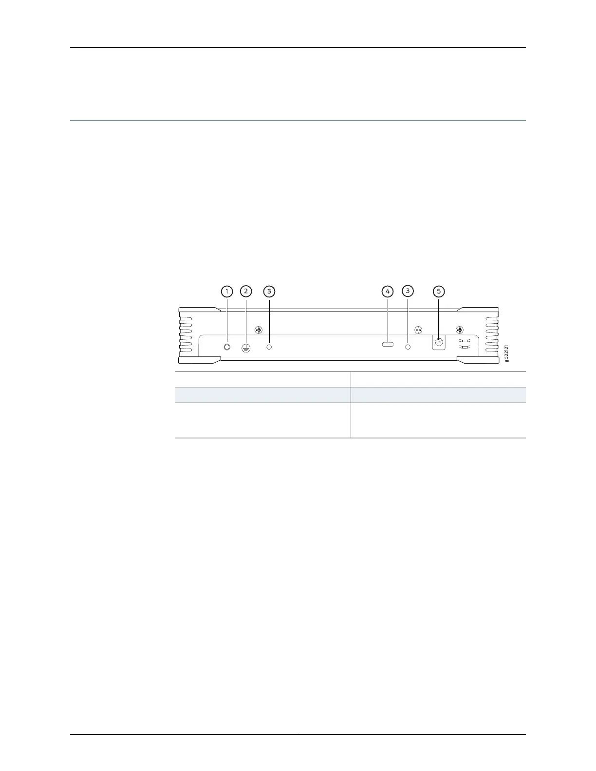
Figure 2 on page 6 shows the rear panel of a WLC100.
Figure 2: Rear Panel of a WLC100 Wireless LAN Controller
4—1— Slot for security cable latchEarth ground connecting point
5—2— Power supply inletEarth ground connecting point label
3—Slot for the screws used to secure the
controller to the rack-mount tray by using
system lock brackets
Related
Documentation
• Front Panel of WLC100 Wireless LAN Controllers on page 5
Copyright © 2013, Juniper Networks, Inc.6
Complete Hardware Guide for WLC100 Wireless LAN Controller