CHAPTER 2
Component Descriptions
•
System LEDs in WLC100 Wireless LAN Controllers on page 7
•
Network Port LEDs in WLC100 Wireless LAN Controllers on page 8
System LEDs in WLC100 Wireless LAN Controllers
The front panel of the WLC100 has two system LEDs—labeled STATUS and POWER—on
the far right side of the panel.
Table 2 on page 7 describes the system LEDs in the WLC100, their colors and states,
and the status they indicate.
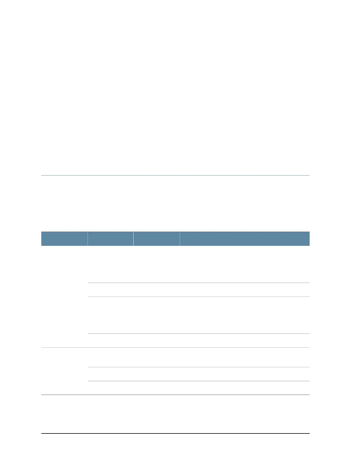
Table 2: System LEDs in WLC100 Wireless LAN Controllers
DescriptionStatusColorLED
Indicates one of the following:
•
The controller is functioning normally.
•
If you had pressed the RESET button, the factory
configuration was loaded successfully.
On steadilyGreenSTATUS
The controller is booting.BlinkingGreen
Indicates one of the following:
•
The controller did not boot correctly.
•
If you had pressed the RESET button, the factory
configuration is being loaded.
BlinkingAmber
The booting is aborted.BlinkingYellow
The power supply is functioning normally and providing
power to the controller.
On steadilyGreenPOWER
The power supply is available, but there is an error.On steadilyAmber
The power supply is off.OffGreen
7Copyright © 2013, Juniper Networks, Inc.