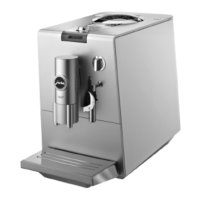
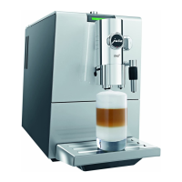
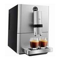
ENA Micro line / IMPRESSA A line
Docu.-name: Demontage_ENA_Micro_EN.docx
L:\Geräte\Linie_A\A5_OT\Schulungsunterlagen\E\Demontag
e_ENA_Micro_EN.docx
Table of contents:
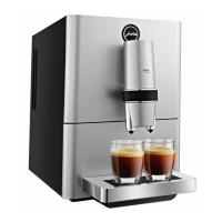
1 Disassembling (example ENA Micro 9 OT): ..............................................................................3
1.1 Service cover / side panel 1
st
generation: ................................................................................... 4
1.2 Service cover / side panel 2
nd
generation and IMPRESSA A line: ................................................. 6
1.3 Disassembling of further components: ....................................................................................... 7
1.4 Coffee spout ENA Micro 5:....................................................................................................... 15
1.5 Coffee spout IMPRESSA A5 OT/A9 OT TFT: .............................................................................. 17
2 View appliance, Right: .......................................................................................................... 19
3 View appliance, Left: ............................................................................................................. 20
4 View appliance, Top: ............................................................................................................. 21
5 View appliance, Back: ........................................................................................................... 21
6 View power-logic print, cable wiring (ENA Micro 9 One Touch): .......................................... 22
6.1 Block schematic ENA Micro 9 OT/IMPRESSA A5 OT: .................................................................. 23
6.2 Blockschema IMPRESSA A9 OT TFT: ........................................................................................ 23
6.3 Block schematic ENA Micro 1/5: ............................................................................................... 24
7 View multi-valve connections ENA Micro 9 OT/ IMPRESSA A5 OT/A9 OT TFT:.................... 25
7.1 Fluid system ENA Micro 9 OT/IMPRESSA A5 OT/A9 OT TFT: ...................................................... 25
7.2 Fluid system ENA Micro 1/5: .................................................................................................... 26
Revision:
A: Remove hose of BU, remove inner distributing collar
B: Image 5
C: Image 7, ENA Micro 1
D: Image 7
E: Added ENA Micro 5
F: IMPRESSA A line added, new chapter numbering
G: Added IMPRESSA A9 OT TFT
 Loading...