Do you have a question about the Jura IMPRESSA J Series and is the answer not in the manual?
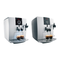
View from the top, unscrew 4x oval-screws for component disassembly.
Unscrew only the left oval-screw as part of component disassembly.
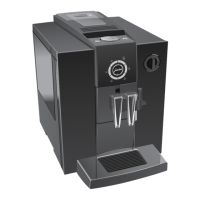
Remove the water tank and tray from the machine.
Turn the JURA emblem on the back anti-clockwise to remove it.
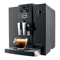
Unscrew two TORX15 screws.
Remove the shield, noting snap-locks located at top and bottom.
Remove the right side case of the appliance.
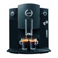
Unscrew TORX15 to slide the left side case backwards.
Remove the spilling cover of the brewing unit.
Remove brewing unit by unscrewing screws and detaching coffee outlet hose.
Unscrew TORX15 to slide power and logic print support leftwards.
Thermoblock-lid fixed with 2 snap-locks; pump removal requires lid removal.
Unscrew TORX15 to remove the thermoblock support.
Remove multi-ceramic-valve support (with drain-magnet) by unscrewing 3x TORX15.
Remove control panel by unscrewing 2x TORX15 from module.
Disconnect 3 connectors, cup lights and control panel for removal.
Remove left and right front covers by lifting them upwards.
Unscrew 2x TORX15 from water/steam tap to remove right front panel.
Clean coffee outlet by unscrewing two TORX9 screws.
Remove coffee outlet by releasing snap-locks and unscrewing TORX8.
View showing the disassembled coffee outlet and TORX8 position.
Unplug cables and detach brewing unit hose to fully remove coffee outlet.
Connect dummy-cable to old feeder for pulling in new feeder.
Replace webbing-hose if clamping spring is loose to maintain density.
Secure the encoder with a clamp.
Check the hinge of the bean tank cover during re-assembly.
Ensure assembled bean tank cover does not move upwards; check hinge if it does.
Use right and left oval-screws to fix the shield.
Unscrew TORX15 to remove the cover hinges.
Remove CAPPU outlet by unscrewing six TORX15 screws.
Remove coffee outlet using TORX8 as shown in image 20.
View of CAPPU support and coffee spout with snap-lock.
View of the CAPPU spout.
Logic connections for the main PCB and related components.
| Programmable Beverages | Yes |
|---|---|
| Pump Pressure | 15 bar |
| Display | TFT color display |
| Power Consumption | 1450 W |
| Adjustable Water Volume | Yes |
| Product Line | IMPRESSA |
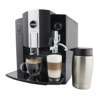
| Coffee Specialties | Espresso, Coffee, Cappuccino, Latte Macchiato |
| Coffee Grounds Container | 16 portions |
| Adjustable Coffee Strength | Yes |