INSTALLATION, USE AND MAINTENANCE MANUAL – LC
Jurop SpA
Via Crosera n° 50
33082 Azzano Decimo, PN (Italia)
TEL. +39 0434 636811 FAX. +39 0434 636812
http://www.jurop.it
e-mail: info@jurop.it
• A limited speed ratio allows a longer belts life while reducing
stress on the shafts. When possible, prefer:
− Pulleys with a pitch diameter bigger than the one indicated;
− Motors or power take-offs with a speed similar to the one of the
pump.
Drive min. pulley p. diam
Operating pressure (max. vac.)
Operating pressure (1 rel. bar)
Max pressure draining line
Max. pressure motor exhaust
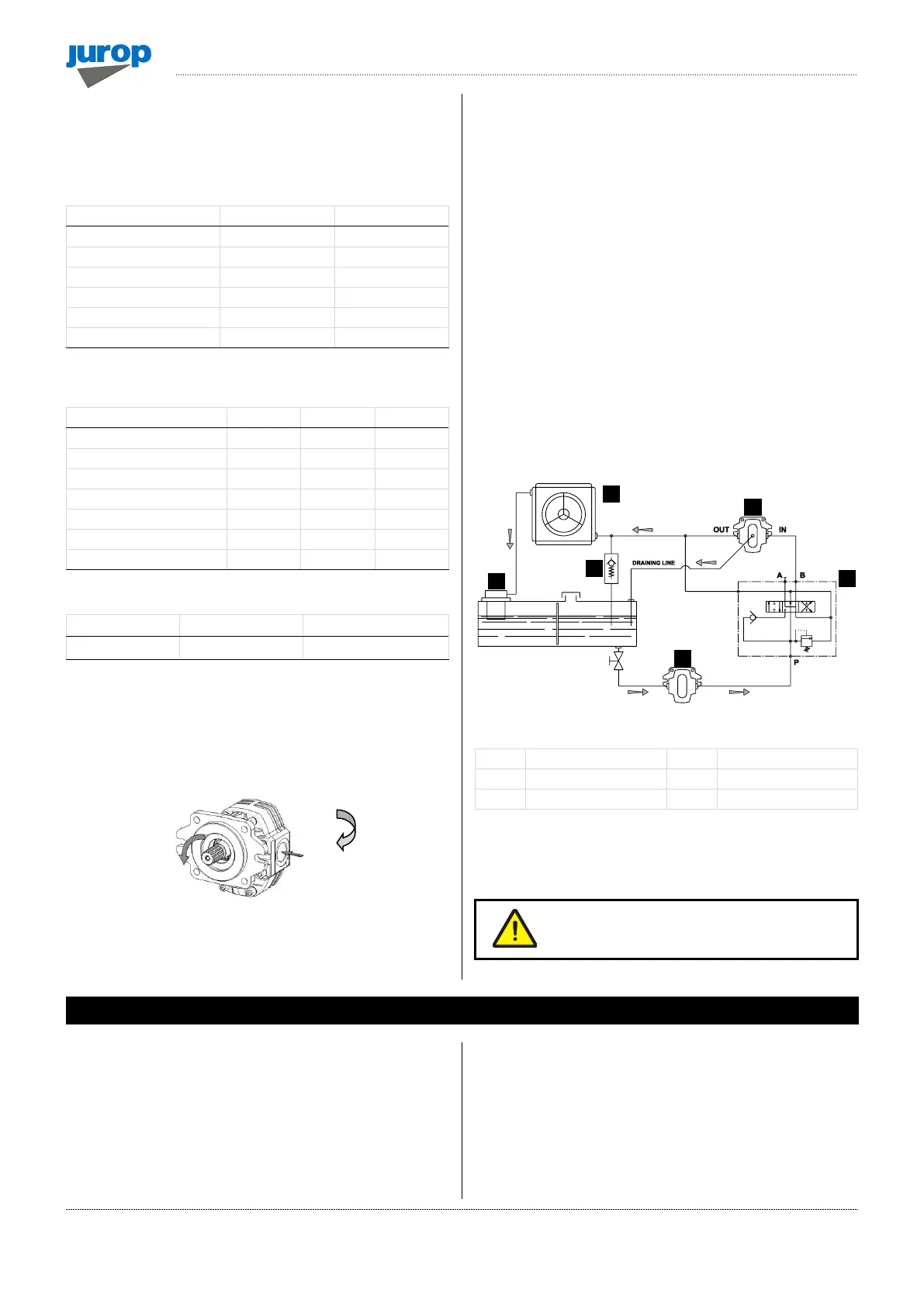
• Fluid: mineral oil for hydraulic systems in compliance with ISO/DIN.
• Filtration: class 19/16 contamination according to ISO 4406 to be
obtained with a ßx = 75 filter.
• Check circuit connections: they must be applied in the same
rotation direction as that indicated by the arrow on the pump front
flange.
Pic. 4.10
• Draining: connect directly to the tank above the maximum oil
level. Operating without draining line may damage the motor.
• Distributor: open-centre distributor in central idle position
(vacuum pump off). It must be equipped with an adjustable
overpressure safety valve.
• Motor pipeline: outlet pipe must not be of a smaller diameter than
that of the inlet port. Inlet pipes always have a diameter smaller than
outlet pipes. Choose preferably flexible pipes to avoid vibration
transmission.
• Tank: with suction pipe and return separated by baffles. If
necessary, use a heat exchanger to avoid oil heating above 70-80°C
and protect it from extreme pressure with a pressure relief valve.
Minimum approximate capacity: as twice as the circulation flow.
• Starting-up: be sure that the system is well cleaned and pour oil
into the tank and into the motor housing (necessary to lubricate the
internal bearings).
• Vent the circuit and adjust the overpressure safety valve to the
lowest possible value.
• Check the oil tank level.
• Increase pressure and rotation speed until operating values are
reached.
Pic. 4.11
* optional components
• The machine/system manufacturer is responsible for dimensioning
the lines.
The machine/system manufacturer is responsible
for dimensioning the lines.
5.1. Starting-up of the pump
Lubrication
• Check oil levels in gearbox and side mounted tank.
• Check the oil level in the gear box (if the pomp is provided with it).
• In order to choose the most suitable oil, see paragraph 2.6.
Cooling
• Unscrew the vent valves on the housing and recycling pump, pour
the cooling fluid through the port near the exchanger.
• Screw the vent valves and start running the cooling system in
order to expel the air bubbles inside it. Then, adjust the level by filling
up the expansion tank on the exchanger: it must be half filled
(approximately).
 Loading...