http://www.jurop.it
e-mail: info@jurop.it
• Replace all the pump vanes at the same time.
Replace the vanes when their wear exceeds 5 mm
(L – L min): they may break. Replace all vanes at
the same time.
• Replace the cap after the measurement.
6.2. Extraordinary maintenance
• Before starting any extraordinary maintenance operation, be sure
the pump stands still and follow the safety prescriptions as described in
Cap. “Safety and accident prevention”.
Replacing the vanes (R260 with rear oil tank)
• Remove the vacuum pump from its bearing frame and wash it
before disassembling.
• It is suggested to remove the oil tank on the rear part because
generally the pump’s drive components are fitted on the front flange.
Use always the specific kit of gaskets for the pump model at hand (see
also spare parts list).
• Material that is subject to wear: replace.
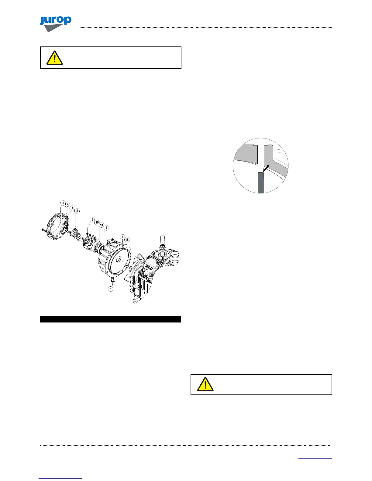
Pic. 6.3
Pos. Code Description
1 1684000000 PLUG 3/8
2 1640101100 TANK’S CAP
3 1680707500 CAP’S GASKET
4 4026706101 PIPE’S FITTING
5 4024251500 OIL PUMP (RIGHT)
4024251000 OIL PUMP (LEFT)
6 4022200111 SEAL 72X48X15
7 1612500300 OIL TANK
8 4022200341 OR
9 1610508500 PUMP’S FLANGE
10 4026300020 COMPENSATION RING
11 4023100140 BEARING
Disassemble operation
• Drain the oil tank through the proper port (pos. 1).
• Remove the tank’s cap (pos. 2) and change the gasket (pos. 3);
unscrew the lubrication pipe’s fittings (pos .4) connecting the oil pump
to the oilers.
• Remove the oil pump (pos .5).
• Remove the screws fixing the oil tank (pos. 7) and carefully
remove it, eventually using two screws partially winded inside the
threads. Avoid that the rotor falls down inside the housing, supporting it
if necessary with adequate tools. Change the OR (pos. 8). Remove the
oil pump’s flange (pos. 9), the compensation ring (pos. 10) and the
bearing (pos. 11) this will make the reassembly of the oil tank much
easier (pos. 7).
• Lubricate the new vanes before inserting them in the rotor’s slots.
• The new vanes have to be inserted with the rounded corner facing
towards the housing (See Pic. 6.4).
Pic. 6.4
Assemble operation
• Reassemble everything again in the right sequence, absolutely
avoiding to leave foreign parts inside the pump. Always change all the
gaskets and the OR after having them properly lubricated and also the
seal (pos. 6) if necessary add some grease in the space between the
bearing (pos. 11) and the flange (pos. 9).
• Reassemble the oil tank (pos. 7) and the OR (pos. 8) carefully
inserting the drive shaft without damaging the seal.
• Insert the bearing (pos. 11), the compensation ring (pos. 10), and
the oil pump’s flange (pos. 9).
• Insert correctly the lubrication pump in the driving slot and refit the
flange.
• Reassemble the lubrication pipes and fittings.
• Reassemble the tank’s cap (pos. 2) and the gasket (pos. 3).
• Replace the plug on the tank (pos. 1) and refill it with lubrication
oil.
M Mounting the hydraulic drive
• We recommend the drive coupling be oiled when vanes are being
replaced.
• However lubricate the drive coupling every 1500 hours.
We recommend the drive coupling be oiled every
1500 hours.
• Apply coupling hub to vacuum pump axis respecting the position
marked during disassembly: the grain must go back into the seat on the
rim.
• Mount the coupling and lubricate internally with NLGI 2 Lithium
grease. Provide an adequate quantity of fat, in order to have a medium
filling.
 Loading...