http://www.jurop.it
e-mail: info@jurop.it
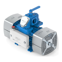
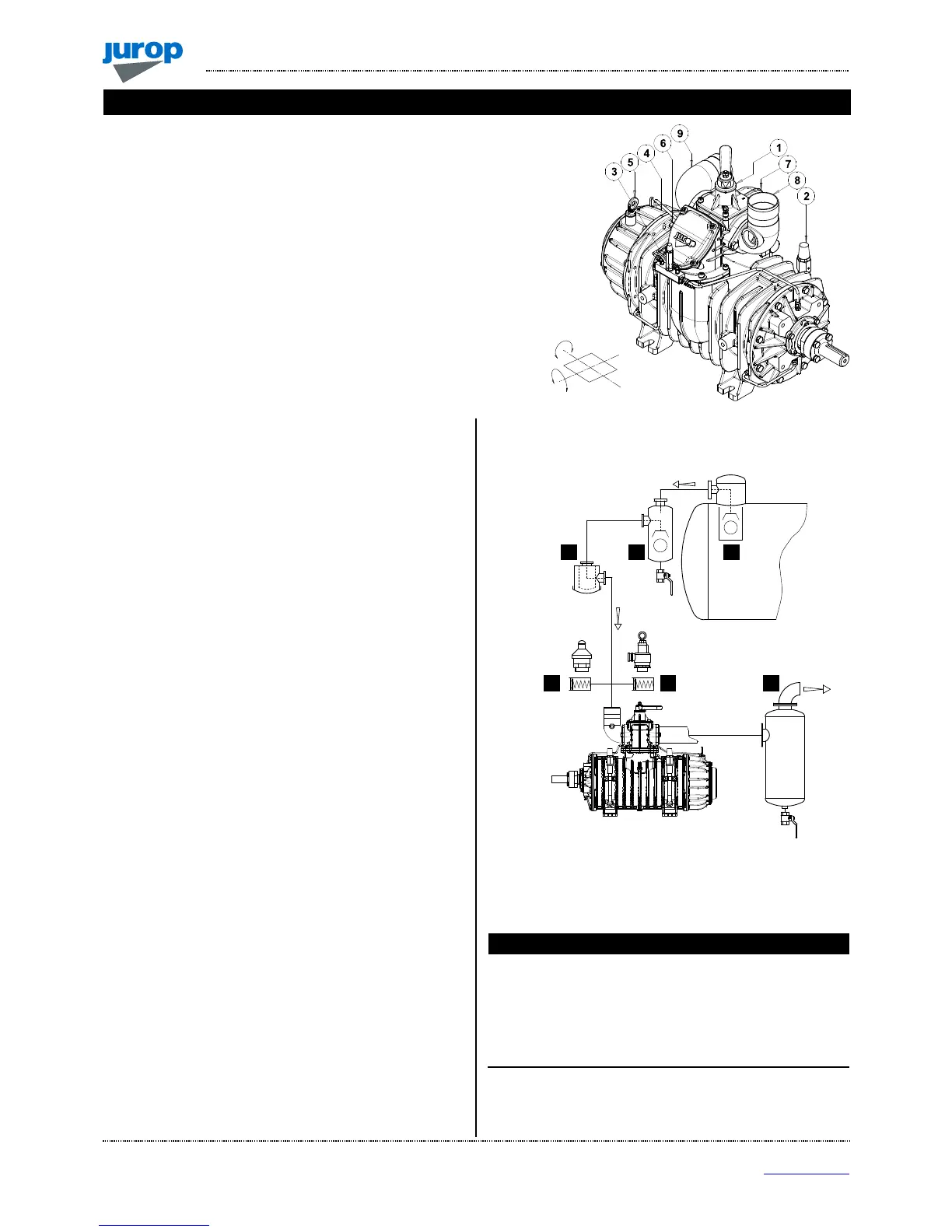
Main components legend
1. Vacuum/Pressure change-over valve 5. Oil filling port and dip stick
2. Air injection valves 6. Vanes inspection port
(with sintered filter) 7. Non-returne valve (Intake manifold)
3. One-way valve 8. Suction conveyor
4. Oil tank 9. Exhaust conveyor
Pic. 4.1
4.1. Checking upon receipt
• When the goods are delivered, make sure that all parts listed on
the delivery note are in perfect condition and have suffered no damage
during shipping.
• Make sure the vacuum pump has its identification plate. Pumps
without such identification are to be considered anonymous and
potentially dangerous: in such an event, they must not be used,
otherwise the manufacturer will be deemed free from any liability
whatsoever.
• Pump must be kept in a dry storage area. During storage, inlet and
outlet ports must be kept closed.
4.2. Storing in the warehouse
• If the compressor will not be installed inside a short time after
delivery:
- Remove the guards from the ports and spray a film of
protective oil over the inner surfaces of the body, rotors and
sides. Then attach again the guards;
- Store in a closed and dry place. Renew the preserving oil
periodically.
• To temporarily store a used pump, follow the instructions below:
- Thoroughly clean the pump.
- Equip the pump with suitable anti-corrosion protection.
4.3. Mounting
• The pump must be assembled for an easy access for maintenance
operations and secured rigidly to a frame or levelled base (max. 3°
slant to the horizontal plane. See Fig. 4.1). The base must be such as
to avoid vibrations, bending or deformation.
• Leave enough space around the pump to allow the free circulation
of air for cooling; avoid exposure to dirt and debris.
• Provide the necessary space to reach all points of lubrication
control (oil level), and the oil tank filler cap, the lever of the 4-way
switch, vanes inspection ports. See Pic. 4.1.
• In case of R260 with hydraulic motor, provide the necessary space
to disassemble the motor itself and proceed with joint lubrication.
4.4. Vacuum / Pressure line
• See picture 4.2.
Pic. 4.2
• The hoses connecting the suction and exhaust ports of the vacuum
pump must be of adeguate diameter (suggested not less than 3”) and of
oil and corrosion resistant materials and before connecting them, make
sure that they are perfectly clean in the inside.
• The weight or dimensions of the pipes must in no way stress the R
body. Use high temperature resistant rubber sleeves.
Vacuum / Pressure line components
1
Primary shutoff
2
Secondary shutoff
3
Suction filter
4 Silencer
5
Over-pressure safety relief valve
6
Vacuum control valve
 Loading...