http://www.jurop.it
e-mail: info@jurop.it
• Remove the port guards when mounting. The pipes and
components of the whole line must be clean.
• Avoid constrictions and tight curves where they are not essential.
• Connect the pump to the tank through the suction manifold (Fig.
4.1 - pos. 8) which has a threaded port for fitting the over-pressure
valve.
• The exhaust pipes can reach high temperatures. Protect those
adequately from the operator reach.
• A clapet valve on suction pipe avoids rotation in the opposite
direction when the pump stops.
• To avoid that foreign liquids will enter the vacuum pump it is
necessary to mount on the suction line an over-flow valve of “floating-
ball” type (Fig. 4.2. - pos. 1). The flow section of this valve must be
equivalent to the suction hose’s one.
• It is also necessary to have on the line a suitable air filter for
preventing solids to be sucked inside the vacuum pump. It is also
recommended to mount a “secondary shutoff” of floating-ball type (Fig.
4.2 - pos. 2) between vacuum pump and over-flow (primary shutoff),
along with the previously mentioned air filter (Fig. 4.2 - pos. 3).
• Called also 4-way valve, normally is manually operated but it can
be at any time transformed in pneumatically or hydraulic operated upon
request of the appropriate kit.
• During normal running of the pump the resulting noise should be
reduced by means of a suitable silencer (Fig. 4.2 - pos. 4) mounted as
close as possible to the pump itself. It has to be dimensioned for the air
flow produced by the pump model. The oil used for the pump’s inside
lubrication has to be separated from the exhausted air by means of an
adequate oil-separator, placed directly inside the silencer. The silencer
is fitted also with a draining tap for the collected oil and condensed
liquids
• Over-pressure safety relief valve. It must be dimensioned to
discharge the entire air-flow of the pump. The adjustement of this valve
has to be kept inside 10% of tollerance of the pump's working pressure
and in any case it has to stay inside the given value of the tank's work
pressure.
• For pumps that reach, during normal operating, discharge air
temperature close to 150 °C (300°F) - (checked at not more than 150
mm from the discharge connection) it is necessary to use a device
(overheating limiter) that will not allow to exceed such temperature.
Contact our Technical Department.
• An adjustable curved pipe is installed on the outlet of the silencer,
in order to prevent rain from entering and to enable positioning (during
installation) of the output airflow.
• Direct the silencer discharge output away from the silencer suction
inlet in order to prevent the input of hot fluids into the injection inlet.
Attention: direct the silencer discharge output
away from the silencer suction inlet.
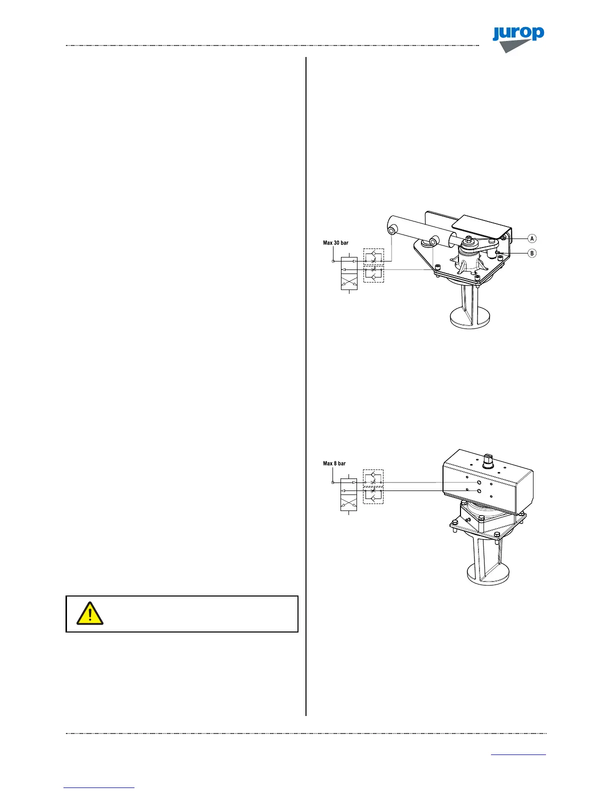
4.5 Hydraulic actuator adjustment
• Extraordinary maintenance operations can require the upper cover
(and that of the actuator, either manual or pneumatic) to be removed.
We recommend ensuring enough space to carry out such operations.
• If the cock blocks or it moves with friction, screw up the clearance
regulation nut (A). Screw up ¼ of turn each time. Block the nut rotation
with the safety nut.
• The lubrication points (B) and the clearance regulation bolt (A)
must be accessible. See Fig. 4.5.
• Lubricate with grease every 1000 cycles. Grease type NLGI 2.
• It is suggested to install 2 one‐way flow controller between the
hydraulic switch and the hydraulic actuator. Set the flow controllers in
order to prevent hard hitting through the end of stroke. Minimum
commutation time: 1 second.
• Maximum feed pressure: 30 bar.
• To order spare parts see spare parts list at the end of this manual.
Pic. 4.3
4.6 Pneumatic actuator adjustment
• In the event of 4-way valves equipped with pneumatic actuator, we
recommend installing two one-way flow regulators between the
pneumatic “control” and the pneumatic actuator. The following figure
shows a schematic view of a possible pneumatic installation.
Pic. 4.4
• We recommend adjusting the two flow regulators in order for
rotation to occur without knocks and with a switching time of at least
one second.
4.7. Pump mounting - drive connection
A) Cardan shaft drive
• Use telescopic cardan shafts.
 Loading...