http://www.jurop.it
e-mail: info@jurop.it
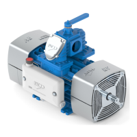
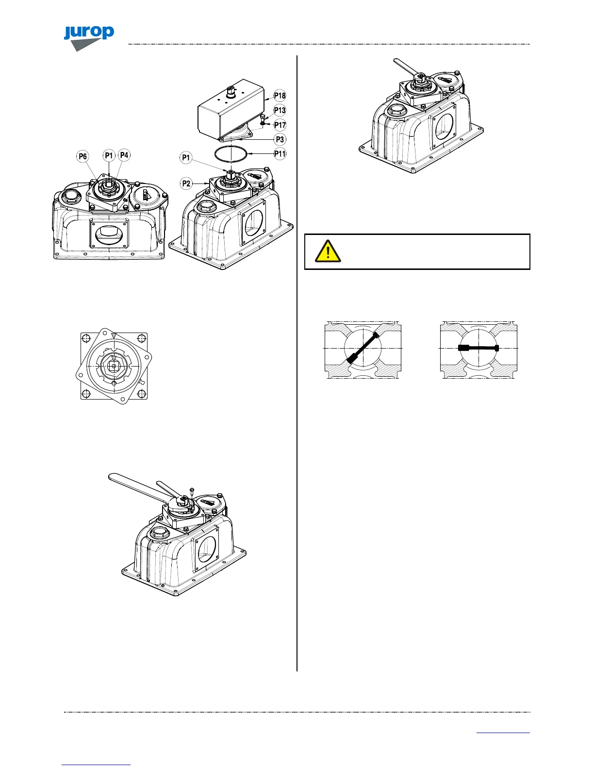
Adjusting the pneumatically operated 4-way valve
• In case of reduced
performance or difficult rotation of
the valve in its seat, it is necessary
to adjust the operating play.
Pic. 6.5
• Unscrew the 4 screws M8x16 which fasten the top cover (P3) to
the inferior support (P2).
• Clean the inner part from the lubricant.
“Mark” the initial position of the
cock (P1). When mounting the
cock back in place, it must be in
the same position.
• Turn the valve until one of the cock regulation ferrules (P6)
coincides with one of the threaded holes on the inferior flange (P2).
Block temporarily the nut ferrule with a screw.
• Hold the valve in place with a 17 mm spanner and loosen the nut
(P4) over the ferrule by ½ - ¾ turn with a 36 mm spanner.
Pic. 6.6
• Valve adjustment: turn the valve clockwise by 1/8 turn (45°) in
order to lower it (in case of excessive play between the valve and its
seat and of reduced performance) or anticlockwise by 1/8 turn (45°) to
raise it (in case of difficult rotation of the valve in its seat).
• Hold the valve in place with the spanner and fasten the nut (P4)
above the ferrule.
Pic. 6.7
• Remove the screw which temporarily blocks the ferrule and check
for the correct rotation of the valve by adjusting the shaft frame. Repeat
the valve adjustment, if necessary.
Attention: get the valve back into the previously
“marked” position. Otherwise, the valve may
work improperly.
• The valve - in both its end stroke positions - must separate the air
flow sucked from the pump outlet air. The pump may be started in
order to check for the proper functioning.
• Lubricate the areas near the ferrule in order to guarantee the
lubrication of parts undergoing wear.
• Set the top cover back into place. Do not forget the OR-Ring (P11).
Fasten the 4 screws.
Replacing the vanes
• Remove the vacuum pump from its bearing frame and wash it
before disassembling.
• We recommend that you work on the pump front.
The following drawings refers to RV520. For RV360 see spare part
data sheet drawings at the end of this manual.
• Material that is subject to wear: replace.
 Loading...