

R
rodgersdanielSep 6, 2025
Why does the playback on my JVC CA-DXU10 sound strange?
- MmullinscraigSep 7, 2025
If the playback sounds strange on your JVC Speaker System, cancel Vocal Masking. Also, cancel Key adjustment.
Why does the playback on my JVC CA-DXU10 sound strange?
If the playback sounds strange on your JVC Speaker System, cancel Vocal Masking. Also, cancel Key adjustment.
What to do if my JVC CA-DXU10 Speaker System remote control is not working?
If you are unable to operate your JVC Speaker System with the remote control, first ensure that there is no obstruction between the remote control and the remote sensor on the system. If there isn't any obstruction, replace the batteries, as the current ones may be exhausted.
Why does the cassette holder on my JVC CA-DXU10 not open?
If the cassette holder on your JVC Speaker System cannot be opened, it may be because the power supply from the AC power cord was cut off while the tape was running. Turn on the system to resolve this.
What causes operations to be disabled on my JVC CA-DXU10?
If operations are disabled on your JVC Speaker System, the built-in microprocessor may have malfunctioned due to external electrical interference. Unplug the AC power cord and then plug it back in to resolve this issue.
What to do if adjustments are suddenly canceled on my JVC CA-DXU10?
If adjustments or settings are suddenly canceled before you finish on your JVC Speaker System, it is because there is a time limit. Repeat the procedure again.
Why is it hard to hear broadcasts on my JVC CA-DXU10 Speaker System?
If it is hard to hear broadcasts clearly on your JVC Speaker System due to noise, check and correct the antenna connections, as they may be incorrect or loose. Additionally, the AM loop antenna might be too close to the system; try repositioning it. Finally, ensure that the FM antenna is fully extended and properly positioned.
Why is the picture from my JVC CA-DXU10 Speaker System blurred or split on the TV screen?
If the picture displayed on the TV screen is blurred or divided into two parts when using your JVC Speaker System, it could be because the system is connected to a TV that does not support progressive video input. Use a compatible TV. Also, verify that the correct color system is selected in the settings.
What to do if the disc tray on my JVC CA-DXU10 Speaker System won't open or close?
If the disc tray on your JVC Speaker System does not open or close, ensure that the AC power cord is properly plugged in. If it is plugged in, Child Lock may be enabled. In this case, disable Child Lock. Also, check if Program Play is active, and if so, cancel Program Play.
What to do if there is no picture on my JVC CA-DXU10 Speaker System screen?
If no picture appears on the screen of your JVC Speaker System, check and correct the video cord connections, as they might be incorrect or loose.
What should I do if my JVC Speaker System disc does not play?
If the disc does not play in your JVC Speaker System, check if you have inserted a DVD Video with an incorrect Region Code. If so, use a DVD with the correct region code. Also, ensure that the disc is placed correctly with the label side up.
Essential safety guidelines for handling the product and performing repairs.
Measures to prevent electrostatic discharge damage to sensitive components.
Important warnings and cautions regarding Class 1 laser product operation.
Step-by-step guide to disassembling the main unit components.
Detailed instructions for removing the DVD changer mechanism assembly.
Procedure for safely disconnecting and removing the main control board.
Instructions for removing and reattaching the critical DVD pickup unit.
Steps for removing the sensor board and SV resistor from the DVD mechanism.
Procedure for accessing the DVD module's test mode for diagnostics.
Steps for initializing the DVD module's EEPROM after component replacement.
Explanation of various DVD check modes and their display outputs.
High-level block diagrams illustrating system interconnections.
Detailed circuit schematics for various sections of the unit.
Visual representation of component placement on printed circuit boards.
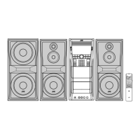
Exploded view and parts list for the DX-U10 general assembly.
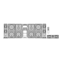
Exploded view and parts list for the DX-U8 general assembly.
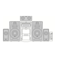
Exploded view and parts list for the DX-U6 general assembly.
Comprehensive list of electrical components for the main board.
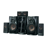
| Brand | JVC |
|---|---|
| Model | CA-DXU10 |
| Category | Speaker System |
| Language | English |