12 (No.PA062<Rev.001>)
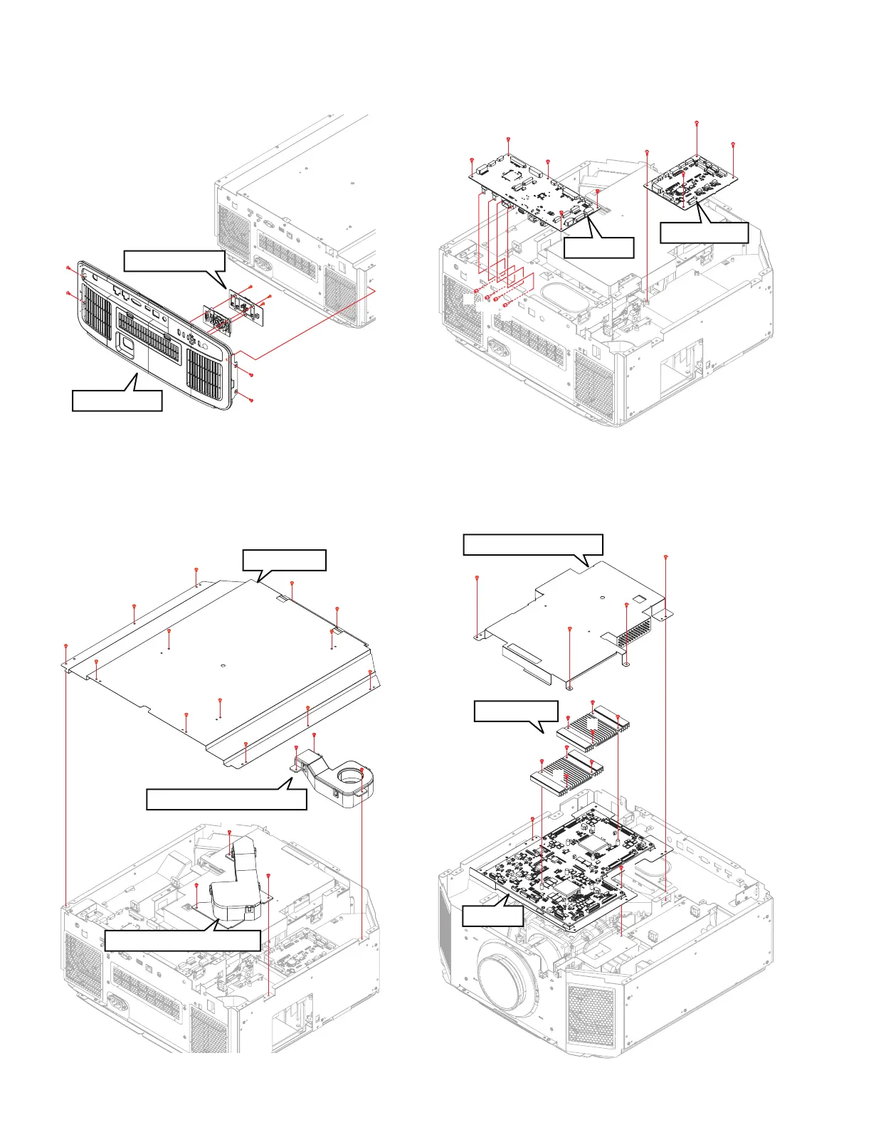
3.2.5 REMOVING THE KEY PAD PWB (Fig.3-5)
(1) Remove the 4 screws (a), and remove the REAR PANEL.
(2) Remove the 3 screws (b), and remove the KEY PAD PWB.
Fig.3-5
3.2.6 REMOVING THE DD FPGA COOLING FAN and DD
ASIC COOLING FAN (Fig.3-6)
(1) Remove the 13 screws (a), and remove the TOP PLATE.
(2) Remove the 3 screws (b), and remove the DD FPGA
COOLING FAN.
(3) Remove the 3 screws (c), and remove the DD ASIC COOL-
ING FAN.
Fig.3-6
3.2.7 REMOVING THE CPU PWB and MOTOR PWB (Fig.3-7)
(1) Remove the 9 screws (a,b), and remove the CPU PWB.
(2) Remove the 4 screws (c), and remove the MOTOR PWB.
Fig.3-7
3.2.8 REMOVING THE DD PWB (Fig.3-8)
(1) Remove the 4 screws (a), and remove the SHIELD CASE
ASS’Y.
(2) Remove the 8 screws (b), and remove the HAET SINK.
(3) Remove the 2 screws (c), and remove the DD PWB.
Fig.3-8
REAR PANEL
a
a
a
b
b
b
a
KEY PAD PWB
TOP PLATE
a
a
a
a
a
a
a
a
a
a
a
a
b
b
c
c
c
a
DD FPGA COOLING FAN
DD ASIC COOLING FAN
b
MOTOR PWB
CPU PWB
b
b
b
b
b
c
c
c
c
a
a
a
a
a
a
a
a
b
c
b
b
b
b
b
DD PWB
HAET SINK
SHIELD CASE ASS'Y
b
c
b
 Loading...