(No.PA062<Rev.001>) 13
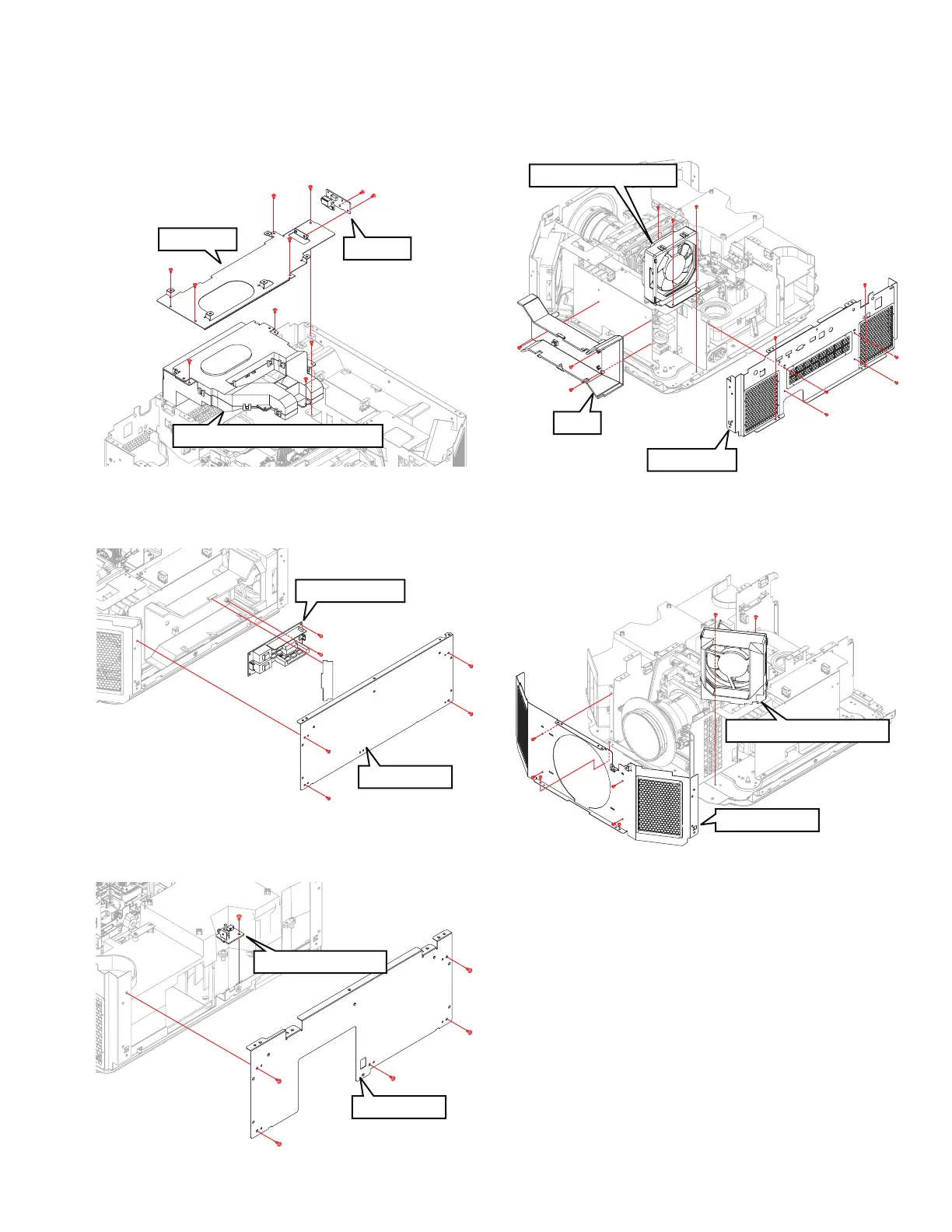
3.2.9 REMOVING THE 3D PWB AND DEVICE COOLING
FAN ASS’Y (Fig.3-9)
(1) Remove the 5 screws (a), and remove the BRACKET.
(2) Remove the 2 screws (b), and remove the 3D PWB.
(3) Remove the 4 screws (c), and remove the DEVICE COOL-
ING FAN ASS'Y.
Fig.3-9
3.2.10 REMOVING THE BALLAST PWB (Fig.3-10)
(1) Remove the 4 screws (a), and remove the SIDE PLATE.
(2) Remove the 2 screws (b), and remove the BALLAST PWB.
Fig.3-10
3.2.11 REMOVING THE INTER LOCK PWB (Fig.3-11)
(1) Remove the 5 screws (a), and remove the SIDE PLATE.
(2) Remove the 1 screw (b), and remove the INTER LOCK PWB.
Fig.3-11
3.2.12 REMOVING THE POWER INTAKE FAN (Fig.3-12)
(1) Remove the 6 screws (a), and remove the REAR BASE.
(2) Remove the 3 screws (b), and remove the DUCT.
(3) Remove the 3 screws (c), and remove the POWER IN-
TAKE FAN.
Fig.3-12
3.2.13 REMOVING THE POWER EXHAUST FAN (Fig.3-13)
(1) Remove the 6 screws (a), and remove the FRONT BASE.
(2) Remove the 2 screws (b), and remove the POWER EX-
HAUST FAN.
Fig.3-13
b
b
c
c
c
a
a
a
a
a
BRACKET
DEVICE COOLING FAN ASS'Y
3D PWB
c
SIDE PLATE
BALLAST PWB
b
b
a
a
a
a
a
SIDE PLATE
INTER LOCK PWB
a
a
a
b
a
DUCT
POWER INTAKE FAN
b
b
b
a
a
a
a
c
c
c
a
a
REAR BASE
POWER EXHAUST FAN
a
a
b
b
a
a
a
a
FRONT BASE
 Loading...