(No.MB376)1-13
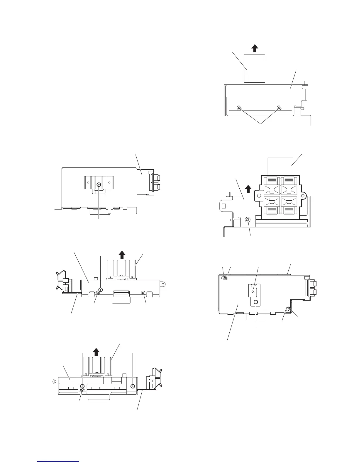
3.1.8 Removing the digital amplifier board
(See Figs.17 to 22)
• Remove the side panels L/R, top panel assembly, rear panel,
switching power supply and digital amplifier board assembly.
(1) From the forward side of the digital amplifier board assem-
bly, remove the screw Q. (See Fig.17.)
(2) From the top and bottom sides of the digital amplifier board
assembly, remove the three screws R. (See Figs.18 and
19.)
(3) Release the joints (h, j, k, m) and remove the shield case
B with the heat sink in the direction of the arrow. (See
Figs.18 to 21.)
(4) From the forward side of the digital amplifier board, remove
the screw R attaching the heat sink. (See Fig.22.)
(5) Remove the solders from the soldered sections (n, p) and
bend the sections (q, r) of the shield case A in the direction
of the arrow. (See Fig.22.)
(6) Take out the digital amplifier board from the shield case A.
Fig.17
Fig.18
Fig.19
Fig.20
Fig.21
Fig.22
Digital amplifier board assembly
Q
Digital amplifier board assembly
hh
Heat sink
R
Shield case B
Digital amplifier board assembly
j
Heat sink
RR
Shield case B
k
Heat sink
Shield case B
m
Heat sink
Shield case B
Digital amplifier board
Shield case A
Heat sink
n
r
q
p
R
 Loading...