(No.MB376)1-15
3.1.12 Removing the DVD mechanism assembly
(See Figs.25 to 28)
• Remove the side panels L/R, top panel assembly, tuner, rear
panel, switching power supply, digital amplifier board assem-
bly, micom board and regulator board.
(1) From the right side of the main body, remove the screw V
attaching the metal chassis. (See Fig.25.)
(2) From the top side of the main body, remove the two screws
W and take out the metal chassis. (See Fig.26.)
Reference:
When attaching the metal chassis, pass the card wire
through the hole t on the metal chassis as before.
(3) Disconnect the card wire from the connector CN703
on the
video board. (See Fig.27.)
(4) Remove the screw X and take out the DVD mechanism as-
sembly from the bottom chassis. (See Fig.27.)
Reference:
When the resolution of DVD mechanism assembly is done se-
quentially, remove a CD fitting in the direction of the arrow.
(See Fig.28.)
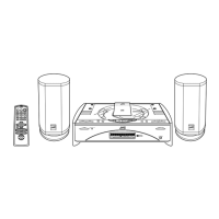
Fig.25
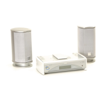
Fig.26
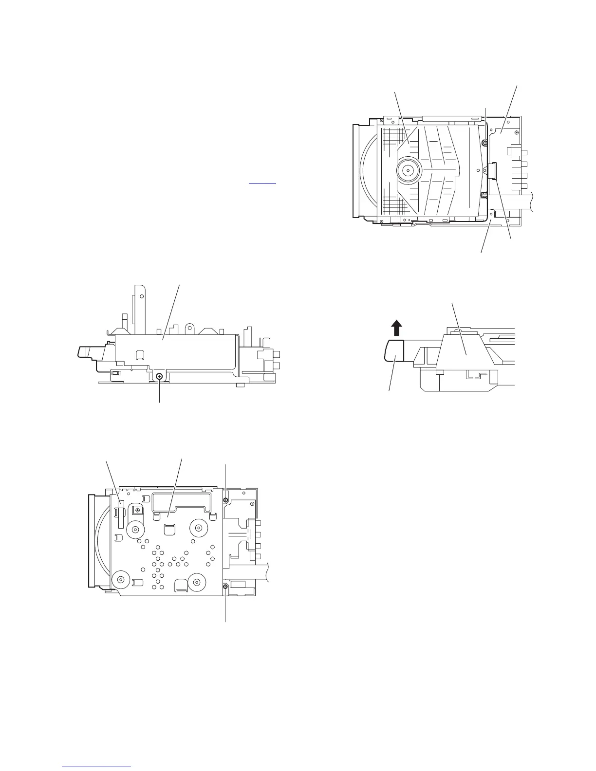
Fig.27
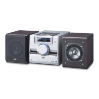
Fig.28
Metal chassis
V
Metal chassis
t
W
W
DVD mechanism assembly
Video board
CN703
Bottom chassis
X
DVD mechanism assembly
CD fitting
 Loading...