65
@
0
!
%^
&
*
(
)
e
t
y r
wq
#
$
1
2
3
4
5
6
7
8
9
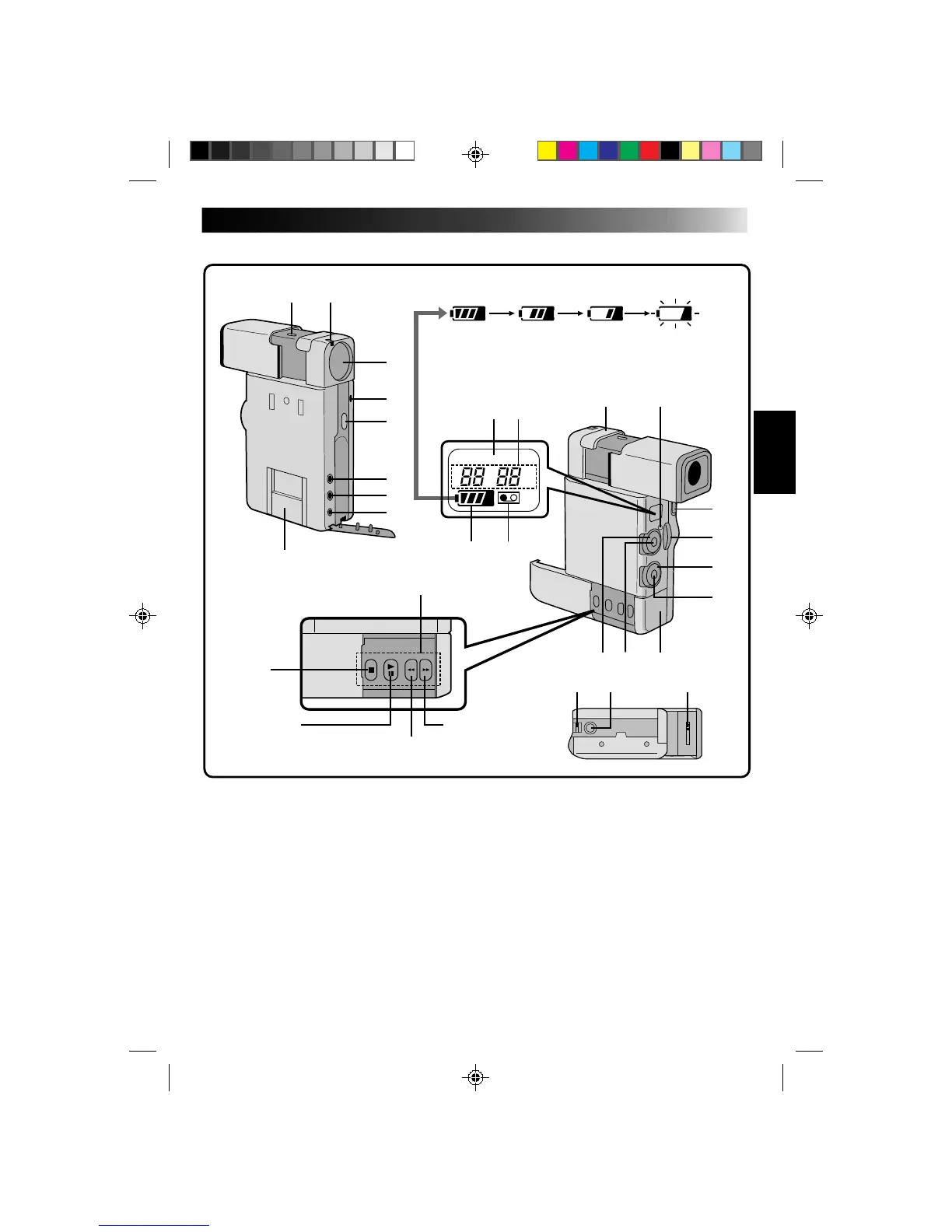
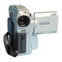
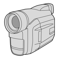
CONTROLS, INDICATIONS AND CONNECTORS
Main Unit
@ Remaining Battery Power Indicator
# “No Tape Loaded” Indicator
$ Tape Advance Buttons (Z pg. 24)
% Stereo Microphone
^ Power Lamp (Z pg. 23)
& OPEN/EJECT Switch (Z pg. 15)
* Zoom Lever (Z pg. 14)
( Select Dial (Z pg. 18)
) SET Button (Z pg. 19)
q Battery Cover (Z pg. 11)
w RECORDING START/STOP Button (Z pg. 23)
e Power Dial (Z pg. 14)
r Diopter Adjust Lever (Z pg. 16)
t Tripod Mounting Socket
y Hand Strap Eyelet (Z pg. 16)
1 MENU Button (Z pg. 19)
2 White Balance Sensor
* Take care not to cover the sensor with your
hand while shooting.
3 Lens
4 Tally Lamp
5 SNAPSHOT Button (Z pg. 25)
6 Ext. Mic Input Jack (Z pg. 12)
7 AV Output Jack (Z pg. 12)
8 DC Input Jack (Z pg. 12)
9 Multi Connector
* Located inside the cover. Connect to the
Docking Station’s multi connector.
0 LCD Display Window
! Remaining Tape Time (during recording)
Time Code (during playback)
(Lights)
Fullly
charged
2/3 Charge
Remaining
1/3 Charge
Remaining
No Charge
Remaining
STOP
BUTTON
PLAY BUTTON
PAUSE BUTTON
FF BUTTON
CAN. BUTTON
REW BUTTON
RE SHOOT BUTTON
Battery Pack Remaining Power Indicator changes as follows
according to the battery pack’s remaining power level:
When the power is almost gone, the indicator blinks, then the
unit shuts off. Replace the battery pack with a fully charged one.