EN85
INDEX
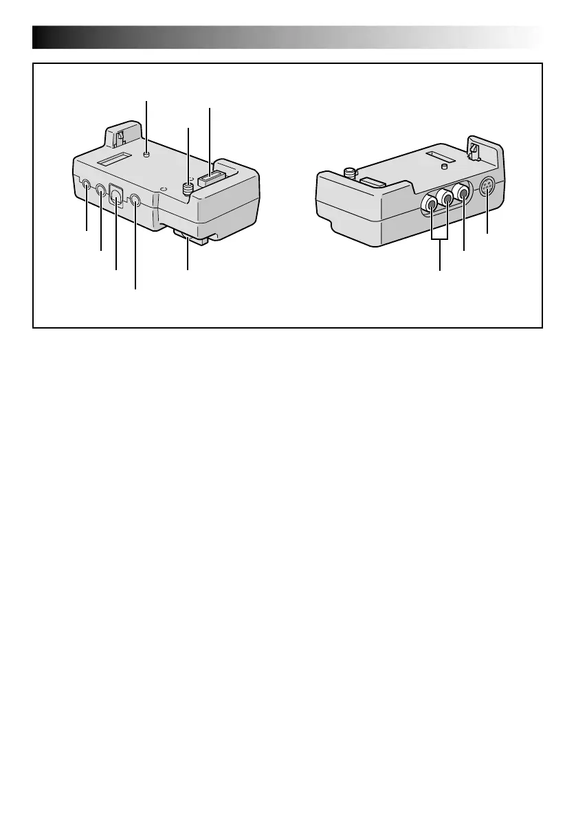
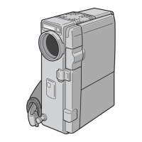
Docking Station
1 PC Connector [DIGITAL STILL] ............ 墌 pg. 58
2 J Terminal/Edit Connector
[JLIP (Joint Level Interface Protocol)
(EDIT)] ................................................ 墌 pg. 71
•Connect to a JLIP-compatible camcorder or
VCR to control it from the computer using the
provided Software.
NOTE:
Make sure that the camcorder is turned on while
connecting the camcorder to a PC using the
Docking Station’s JLIP connector. If the camcorder
is turned off (because the POWER Switch is set to
“OFF” or due to Auto Shut Off* etc.) while the
JLIP programme software is used, it will be
impossible to control the connected devices from
the computer. In such a case, first try turning the
camcorder on again, or unplug the JLIP connec-
tion cable from the Docking Station’s JLIP
connector. Then, initialise or run the software
again.
* Auto Shut Off:
If 5 minutes elapse in the Record-Standby mode
or in the Pause mode, the camcorder’s power
shuts off automatically to conserve energy.
•Connect the editing cable when performing
Random Assemble Editing ......... 墌 pg. 70 – 75
5
6
7
1
4
3
!
2
8
9
0
3 PRINTER Connector
Connect to the optional printer equipped with a
PRINT DATA connector. Refer to the separate
“FOR OWNERS OF AN OPTIONAL PRINTER”
instruction sheet.
4 External Stereo Microphone Input
Connector [MIC] ................................. 墌 pg. 76
5 Stud .................................................... 墌 pg. 56
6 Screw .................................................. 墌 pg. 56
7 Multi Connector
The Docking Station can be connected with this
camcorder through this connector. Never touch it
with your hand or hit it with a hard object; if the
pins are damaged, the connectors will become
unusable due to contact failure.
8 S-Video Input/Output Connector
[S] ................................................. 墌 pg. 56, 71
9 Video Input/Output Connector
[VIDEO] ........................................ 墌 pg. 56, 71
0 Audio Input/Output Connectors
[AUDIO L/R] ................................. 墌 pg. 56, 71
! Screw Knob ......................................... 墌 pg. 56
To attach the camcorder, tighten this clockwise.
Downloaded from: https://www.usersmanualguide.com/