76
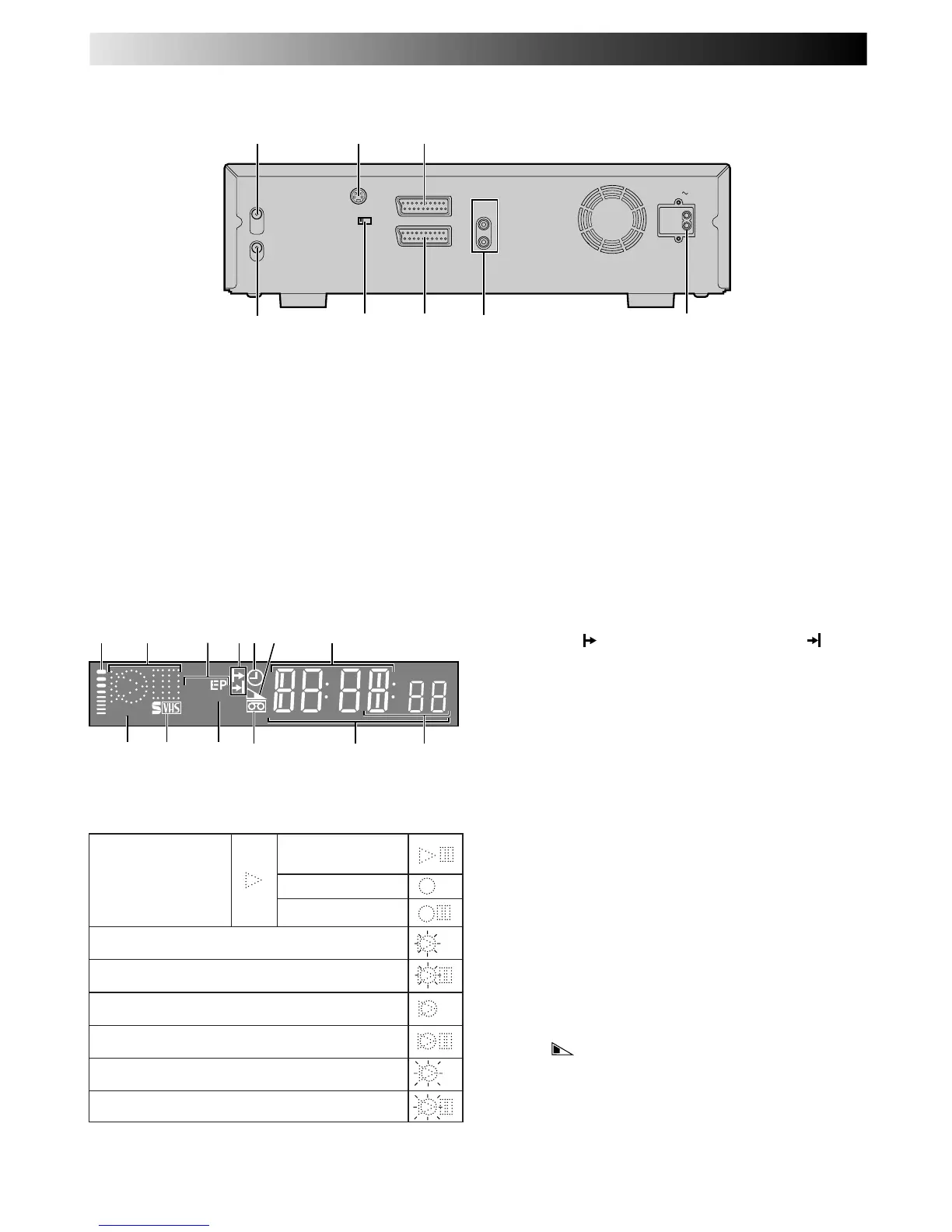
AV1 OUT
COMP. Y/C
S OUT
(DV/VHS)
RF OUT
ANT. IN
AUDIO
OUT
(DV/VHS)
L
R
AV1 IN/OUT (L-1)
AV2 IN/DECODER (
L-2
)
AC IN
2
4
1 3
65 7 8
1 ANT. IN Connector enables connection of aerial.
Z pg. 6, 7
2 S OUT Connector enables S-VIDEO connection to
TV or second recorder.
Z pg. 7, 42
3 AV1 IN/OUT Connector enables AV connection to
TV or second recorder; input recordable when "L-1"
selected.
Z pg. 6, 42
4 RF OUT Connector enables connection to aerial
terminal of TV receiver.
Z pg. 6, 7
5 AV1 OUT Switch selects the type of signal output via
the 21 pin AV1 IN/OUT connector.
Z pg. 6, 57
REAR VIEW
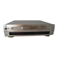
VHS DISPLAY PANEL
1 B.E.S.T. Picture System Display lights from bottom to
top while B.E.S.T. is active. Z pg. 24
2 Symbolic Mode Indicators
3 Tape Speed Indicators display mode of recording; light
during Record or Play mode.
Z pg. 15
* EP is only for NTSC playback.
SP
VCR
VPS/PDC
VPS/PDC
098
!
@
2 71
3 5 64
#
STILL:
SLOW:
RECORD:
RECORD PAUSE:
PLAY:
FF/REW VARIABLE
SEARCH:
AUDIO DUBBING:
AUDIO DUBBING PAUSE:
INSERT:
INSERT PAUSE:
AUDIO DUBBING INSERT:
AUDIO DUBBING INSERT PAUSE:
6 AV2 IN/DECODER Connector enables connection of
satellite receiver, decoder or second recorder; input
recordable when "L-2" selected.
Z pg. 42, 57
7 AUDIO OUT (L/R) Connectors enable
connection of audio cassette recorder, TV or second
video recorder for dubbing.
Z pg. 58
8 Mains Power Inlet enables connection to a mains
outlet using the provided Mains Power Cord.
Z pg. 6, 7
4 Programme Time Indicators show the programme
start time (
) and the programme stop time ( ) for
timer-recording.
Z pg. 20
5 "Timer" Indicator lights when ‰ has been pressed to
engage Timer mode.
Z pg. 19, 21
6 Tape Remaining Time Indicator displays time remaining
on tape when certain buttons are pressed.
Z pg. 17
7 Channel Display shows preset position where the
station currently being received is stored.
Clock Display shows current time.
Z pg. 10
8 PDC Indicator lights when PDC has been engaged
for timer recording.
Z pg. 19, 21
* VPS (Video Programme System) recording is not currently
available in the U.K. and not possible with this recorder.
9 S-VHS Indicator lights when a cassette marked S-VHS
is inserted with S-VHS mode set to "AUTO", and when
an S-VHS-recorded tape is played back.
Z pg. 23
0 VCR Indicator lights when the video recorder is in
the video mode. At this point, the TV automatically
enters AV mode.
Z pg. 12
! "Cassette Loaded" Mark lights once a cassette is
inserted; remains lit until cassette ejected.
@ Counter shows time elapsed since playback or
recording began.
With
displayed, shows time remaining from
current tape position to end of tape (Z pg. 17).
Counter, Preset Position*, Clock and Tape Remaining
Time Display appear alternately when – –:– –
(DISPLAY) is pressed.
* Preset Position is not displayed during playback.
# Mode shows external input mode selected (L-1, L-2 or
L-3).
SUBSIDIARY INFORMATION (cont.)