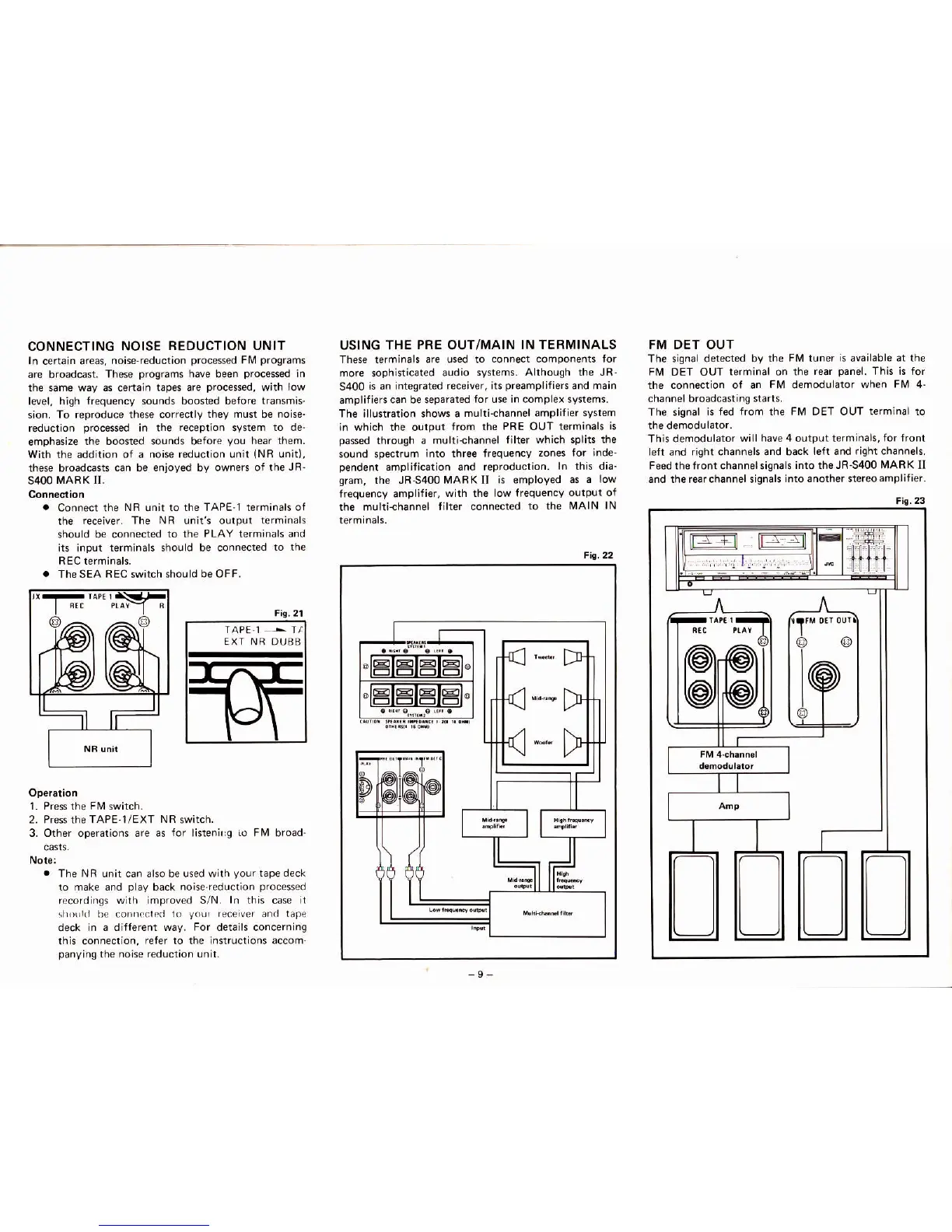
CONNECTING NOISE
REDUCTION UNIT
ln certain areas,
noise-reduction
processed
FIV
programs
are broadcast.
These
programs
have been
processed
in
the siime wav
as
c€rtain
tapes are
processd,
with
low
l€vel,
high frequency sounds boosted beforc
transmis.
sion.
To reproduce these correctly
they must
be
noise.
reduction
processed
in the
reception
system
to de.
emphasize
the boosted sounds before
you
hear them.
With the addition
ol a noise reduction unit
(NR
unit),
these broadcasts
can be enioyed by owners of the
JR-
s400
tvlARK Il.
.
Connect the
Nff
unit to
the TAPE.I terminah of
the
receiver. The NR unifs output
terminals
should be connected
to the
PLAY
terminals
and
its input
terminals should be connected
to ihe
REC terminals.
.
The SEA
FEC
rwitch
should be OFF.
Opera
on
L Press the FtV swhch.
2 Pres rhe TAPE-l/EXT NR switch.
3. Other operations are as
for
listenirg
io Flvl
broad-
.
The NR unit can also be used with
your
tape deck
ro
make and
play
back noise.reduction
processed
recordinss wilh improved S/N.
ln this
case
t
njoril(l be conncdcd 1o
your
r€ceiver and lap€
deck in d dillerenl way. For derdils concerning
this connection,
refer to the instructions accom.
panying
the noise reduction unit,
USING THE
PRE
OUT/MAIN
IN TERMINALS
These
terminak
are used to
connect compon€nts for
more
sophisticated
audio
systems. Ahhough the JR.
5400
is an integrated
receiver, hs
preamplifien
and main
amplifiers
can be separated
for use in complex systems.
The illustration shows a
multi{hannel amplifier
system
in which the output
from the PRE OUT
terminals is
oassed
throuoh a
muhi-channel filter
which splits the
sound sp€ctrum
into three frequency
zones for inde_
pendent
amplification and reproduction.
ln this dia_
sram,
the JR-5400MARKII
is employed as
a low
frequency ampliti€r,
with the low frequency
output of
the multi-channel
filter connected
to the IVAIN
lN
FM DET OUT
The rignal detected by
the FIV tuner is available
at
the
Fl,
DET OUT
terminal on the
rear
panel.
This is for
the
connection of an
FlVl
demodulator
when FM 4-
channel broadcasting
starts.
The signal
is fed from the FlVl DET OUT terminal to
This demodulator
witl have 4 output terminah,
for front
left
and
right channels and back
lelt and right channels.
Feed the front channelsign.ls
into the JR_5400
MARK
II
and the rearchannel rign€ls
into another stereoamplifier.
Fio,22
Fio.23
ffiil
|l:t
!
1'M
0t100r
o@
Fi!,2r
I
 Loading...