Do you have a question about the JVC KD-2A and is the answer not in the manual?
Detailed technical parameters including speed, response, S/N, etc.
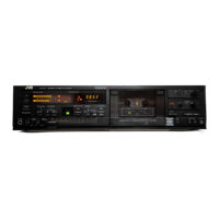
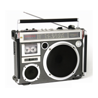
Highlights compact design, ANRS, and portability.
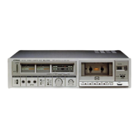
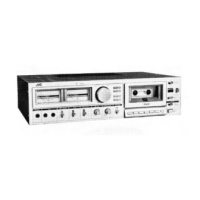
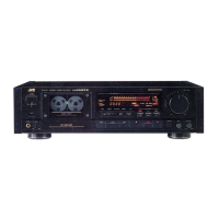
Identifies and describes all front and rear panel controls and jacks.
Diagram showing the location of major internal components.
Step-by-step guide for disassembling the unit's casing.
Procedures for removing electrical components like boards and transformers.
Procedures for removing mechanical assemblies and parts.
Steps for calibrating electrical performance parameters.
Calibration steps for tape playback performance.
Calibration steps for recording and playback.
Procedure for setting the bias current.
Adjusting REC/PB levels and checking distortion.
Measuring S/N and erasure ratios.
Steps for calibrating the ANRS circuit.
Procedures for checking battery and power usage.
Diagram indicating the location of adjustment potentiometers.
Precautions for working with flexible printed circuit boards.
Adjusting head alignment and height for optimal performance.
Calibrating motor speed and torque.
Measuring fast forward torque.
Adjusting rewind torque and auto-stop mechanism.
Identifying and fixing components causing wow and flutter.
Guide for cleaning heads, pinch rollers, and capstans.
Procedures for demagnetizing heads and lubricating parts.
Instructions for cleaning the external unit casing.
Visual representation of the unit's functional blocks.
Component layout diagram for the main amplifier board.
Detailed list of components on the main amplifier board.
Component layout diagram for the REC amplifier board.
Detailed list of components on the REC amplifier board.
Component layout diagram for the ANRS circuit board.
Detailed list of components on the ANRS circuit board.
Illustrated breakdown of mechanical parts (Group 1).
Illustrated breakdown of mechanical parts (Group 2).
Detailed list of all mechanical components with part numbers.
List of enclosure and electrical parts excluding circuit boards.
Illustrated assembly of enclosure and electrical parts (Diagram 1).
Illustrated assembly of enclosure and electrical parts (Diagram 2).
Diagrams showing electrical connections between components and boards.
Complete schematic diagram of the cassette deck's circuitry.
List of included accessories and optional items with part numbers.
Information regarding the packing list and materials for shipping.
| Brand | JVC |
|---|---|
| Model | KD-2A |
| Category | Cassette Player |
| Language | English |