Do you have a question about the JVC KD-A66 and is the answer not in the manual?
Detailed technical parameters including tape speed, frequency response, distortion, and noise.
Details on crosstalk, harmonic distortion, bias, and erasure characteristics.
Information on motors, heads, and semiconductor counts.
Details on input/output terminals, power requirements, and consumption.
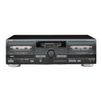
Lists the advanced capabilities and technologies of the cassette deck.
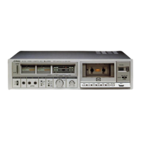
Identifies front panel controls and rear panel connections for operation and setup.
Describes the function of various LED indicators on the unit.
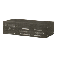
Identifies major front panel, mechanical, and electrical components.
Explains the automatic tape tuning system, including bias, equalizer, and sensitivity.
Summarizes the benefits of automatic tape adjustment for optimal performance.
Step-by-step guide on how the automatic tape tuning process works.
Explains the purpose and operation of the service switch for adjustments.
Details the circuit responsible for automatically adjusting tape bias current.
Explains the circuits for setting equalization level and tape sensitivity.
Describes the circuit for stable analog-to-digital conversion of audio signals.
Explains how marker signals are used for accurate tape positioning.
Details the role and operation of the microcomputer in controlling the deck.
Explains the mechanisms for automatic tape stop and rewind functions.
Instructions for cleaning heads, pinch rollers, and the cabinet.
Procedure for demagnetizing the tape heads to prevent noise.
Steps for disassembling external parts like the cassette door and top cover.
Instructions for removing control knobs and the front panel assembly.
Procedures for removing P.W. boards and related electrical components.
Steps for disassembling the main mechanical unit and chassis.
Lists and identifies key mechanical parts like heads, motors, and reels.
Lists necessary tools and test tapes for calibration procedures.
Covers head alignment, tape contact, and general troubleshooting hints.
Procedure for aligning the playback head for optimal signal output.
Steps to ensure proper tape contact with the heads for accurate recording.
Details adjustments for erase head height, motor speed, torque, and wow/flutter.
Identifies common causes and repairs for wow and flutter problems.
Diagrams showing adjustment points on the main amplifier P.W. board.
Procedures for adjusting playback level and checking frequency response.
Steps for calibrating VU meters and setting recording levels.
Procedures for checking record/playback distortion, S/N ratio, and erasing efficiency.
Steps for calibrating the computer clock and oscillation circuits using a tester.
Procedures for adjusting digital regulation and tape sensitivity via tester.
Steps for calibrating equalization level and bias current using the computer tester.
Schematic overview of the signal path during recording.
Schematic overview of the signal path during playback.
Diagram illustrating the mechanical control circuitry.
Diagram showing the connections and components of the computer circuit.
Information and equivalent circuits for the UPC4557C integrated circuit.
Information and equivalent circuits for the HD7400 integrated circuit.
Information and equivalent circuits for the LB1436 integrated circuit.
Detailed schematic of the main amplifier section.
Detailed schematics for filter and bias control circuits.
Detailed schematic of the mechanical control system.
Detailed schematics for power supply and solenoid control circuits.
Wiring connections for the main amplifier P.W. board.
Wiring connections for power supply and other P.W. boards.
Wiring connections for mechanical control and other P.W. boards.
Internal block diagram of the AN7362N audio processing IC.
Internal block diagram of the M54886P control IC.
List of external enclosure and electrical parts with part numbers.
Continuation of the list for external enclosure and electrical parts.
Exploded view showing the layout of enclosure and electrical parts.
Exploded view illustrating the arrangement of mechanical components.
List of mechanical components with part numbers and descriptions.
Continuation of the list for mechanical components.
List of components found on the main amplifier P.W. board.
Continuation of the list for main amplifier P.W. board components.
Further continuation of the list for main amplifier P.W. board components.
List of components found on the computer P.W. board.
Continuation of the list for computer P.W. board components.
List of components on the mecha control P.W. board, with diagrams.
Specifies knob positions for proper packing.
Lists materials used for packaging the unit.
Lists accessories provided with the cassette deck.
| Brand | JVC |
|---|---|
| Model | KD-A66 |
| Category | Cassette Player |
| Language | English |