(No.MA232)1-9
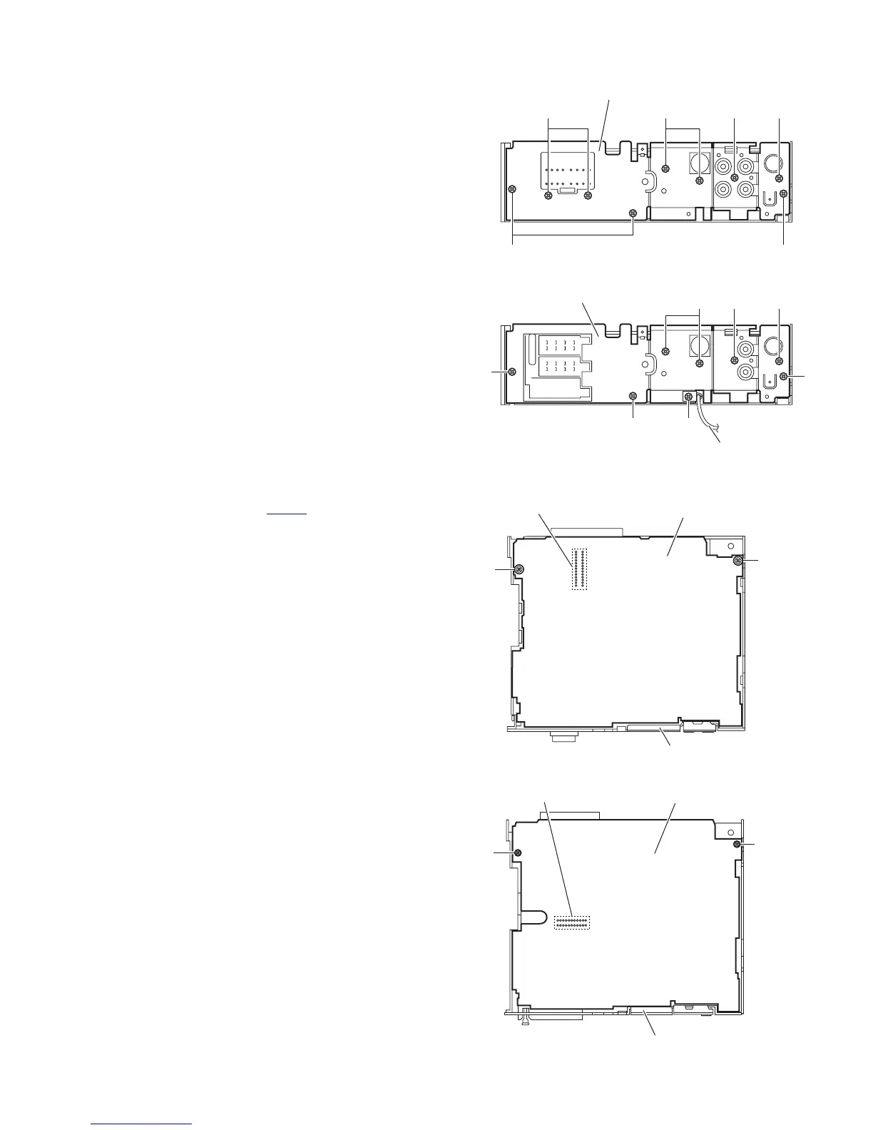
3.1.5 Removing the rear bracket
(See Fig.6)
[For KD-AR470, KD-G420, KD-G524 and KD-G525]
• Remove the bottom cover.
(1) Remove the three screws E, three screws F and three
screws G attaching the rear bracket on the back side of the
main body.
(2) Take out the rear bracket.
3.1.6 Removing the rear bracket
(See Fig.6)
[For KD-G521 and KD-G527]
• Remove the bottom cover.
(1) Remove the three screws E, three screws F and screw G
attaching the rear bracket on the back side of the main
body.
(2) Remove the screw H attaching the steering remote cable
on the rear bracket. [KD-G521 only]
(3) Take out the rear bracket.
3.1.7 Removing the main board
(See Figs.6 and 7)
• Remove the front panel assembly, bottom cover, front chassis
assembly and side panel.
(1) Remove the three screws E attaching the rear bracket on
the back side of the main body. (See Fig.6.)
(2) Remove the two screws J attaching the main board. (See
Fig.7.)
(3) Disconnect the connector CN101
and take out the main
board. (See Fig.7.)
Reference:
Remove the rear bracket as required.
Fig.6
Fig.7
F
E E
Rear bracket
GFG
[For KD-AR470, KD-G420, KD-G524 and KD-G525]
E
F
Rear bracket
E
E
FG
H
Steering remote cable [KD-G521 only]
[For KD-G521 and KD-G527]
Main board
J
J
CN101
Rear bracket
[For KD-AR470, KD-G420, KD-G524 and KD-G525]
[For KD-G521 and KD-G527]
Main board
J
J
CN501
Rear bracket
 Loading...