1-14 (No.MA236)
3.1.6 Removing the main board
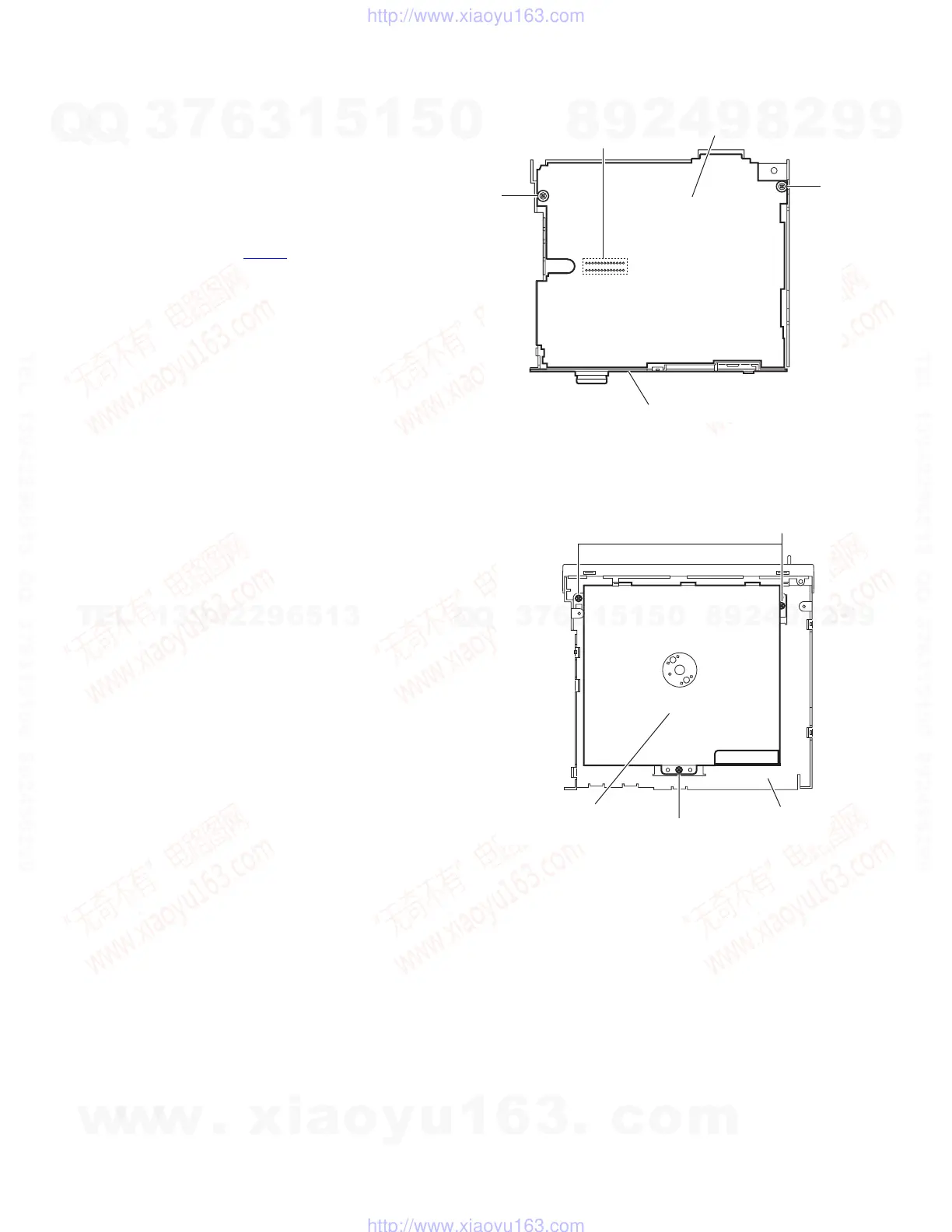
(See Figs.5 and 6)
• Remove the front panel assembly, bottom cover and side pan-
el.
Reference:
Remove the front chassis assembly as required.
(1) Remove the three screws D attaching the rear bracket on
the back side of the main body. (See Fig.5.)
(2) Remove the two screws G attaching the main board. (See
Fig.6.)
(3) Disconnect the connector CN501
on the main board from
the main body and take out the main board with the rear
bracket. (See Fig.6.)
Reference:
Remove the rear bracket from the main body as required. (See
"3.1.5 Removing the rear bracket".)
Fig.6
3.1.7 Removing the CD mechanism assembly
(See Fig. 7)
• Remove the front panel assembly, bottom cover, side panel,
rear bracket and main board.
Reference:
Remove the front chassis assembly as required.
(1) Remove the three screws H attaching the CD mechanism
assembly on the top chassis.
(2) Take out the CD mechanism assembly.
Fig.7
Main board
G
G
CN501
Rear bracket
H
H
CD mechanism assembly
Top chassis
w
w
w
.
x
i
a
o
y
u
1
6
3
.
c
o
m
Q
Q
3
7
6
3
1
5
1
5
0
9
9
2
8
9
4
2
9
8
T
E
L
1
3
9
4
2
2
9
6
5
1
3
9
9
2
8
9
4
2
9
8
0
5
1
5
1
3
6
7
3
Q
Q
TEL 13942296513 QQ 376315150 892498299
TEL 13942296513 QQ 376315150 892498299
http://www.xiaoyu163.com
http://www.xiaoyu163.com
 Loading...