KD-SX998R,KD-SX997R
1-6 (No.49819)
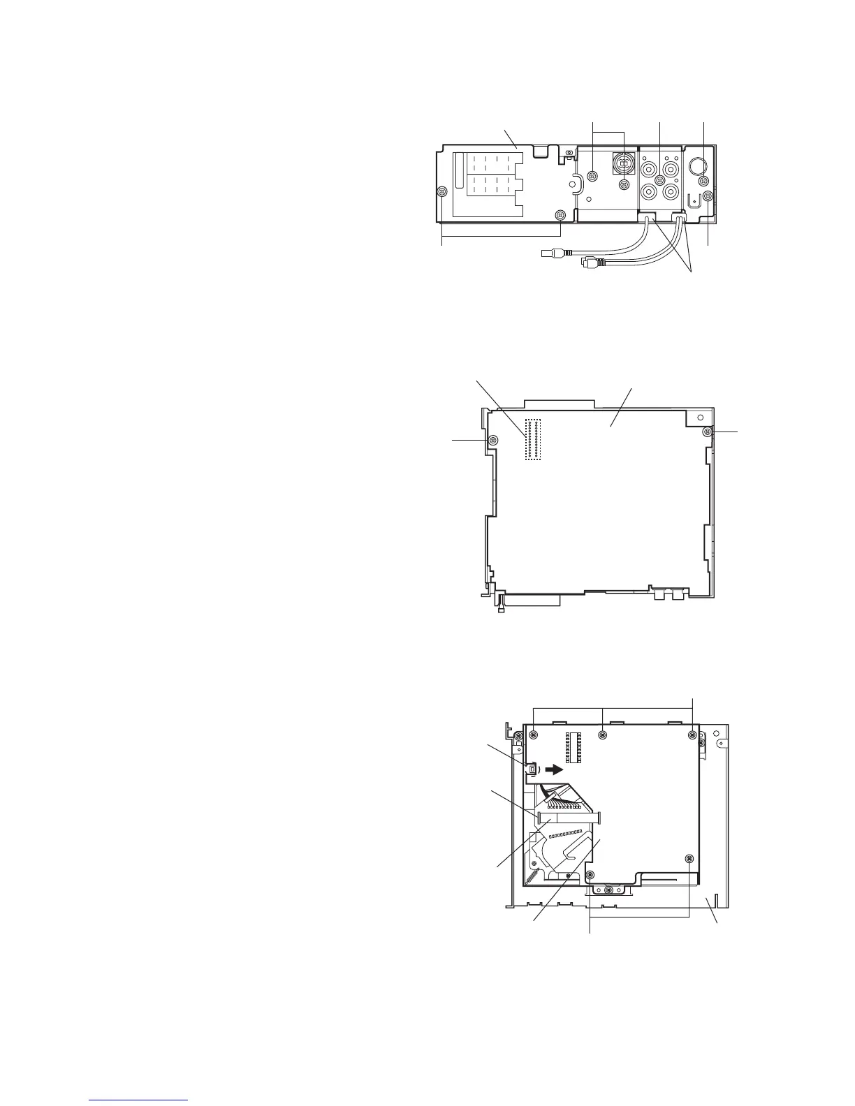
2.1.5 Removing the rear bracket
(See Fig.8)
• Prior to performing the following procedure, remove the front
panel assembly, front chassis assembly, heat sink and bottom
cover.
(1) Remove the three screws E, one screws F and three
screws G on the back of the main body.
(2) Remove the rear bracket.
REFERENCE:
During reassembly, before fixing the rear bracket onto the
main body, insert the Subwoofer cable into the slot.
Fig.8
2.1.6 Removing the main board
(See Fig.9)
• Prior to performing the following procedure, remove the front
panel assembly, front chassis assembly, heat sink, bottom
cover and rear bracket
(1) Remove the two screws H attaching the main board.
(2) Disconnect the connector CN101 and remove the main
board.
Fig.9
2.1.7 Removing the CD mecha board
(See Fig. 10)
• Prior to performing the following procedure, remove the front
panel assembly, front chassis assembly, heat sink, bottom
cover, rear bracket and main board.
(1) Remove the five screws J attaching the CD mecha board.
(2) Disconnect the card wire from the mecha connector.
(3) Move the CD mecha board in the direction of the arrow to
release it from the joint f.
Fig.10
G
EE
F
Rear bracket
G
Insert Subwoofer and steering
cables into the slots.
Main board
H
H
CN101
J
J
Mecha control board
Mecha
connector
Card wire
Top chassis
Joint g
 Loading...