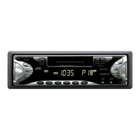
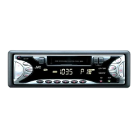
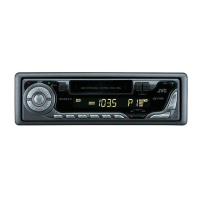
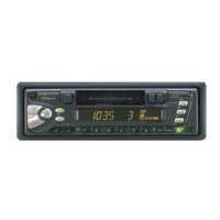
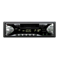
The JVC KS-F171 is a cassette receiver, designed for car audio systems. This service manual provides comprehensive information for its maintenance, adjustment, and repair.
Function Description
The KS-F171 functions as a car audio cassette receiver, integrating both a cassette player and an AM/FM radio tuner. It features a detachable control panel for security and convenience. The device is capable of playing cassette tapes and receiving radio broadcasts across specified frequency bands.
Important Technical Specifications
Audio Output:
- Maximum power output: 45W x 4 channels.
- Speaker load impedance: 4Ω (4Ω to 8Ω allowance).
- Line out level/impedance: 1.0V/20kΩ load (250 nWb/m).
Tuner Section:
- FM Band: 87.5 MHz to 107.9 MHz.
- AM Band: 530 kHz to 1710 kHz.
Standard Volume Position (for adjustment):
- Balance, Bass, Treble volume, Fader: Center (Indication "0").
- Loudness, Dolby NR, Sound, Cruise: Off.
- Volume position: Approximately 2V at speaker output under specified conditions (playback of test tape VT721).
AM Mode (for adjustment):
- Frequency: 999kHz.
- Signal strength: 62dB, INT/400Hz.
- Modulation signal: 30% on receiving.
FM Mono Mode (for adjustment):
- Frequency: 97.9MHz.
- Signal strength: 66dB, INT/400Hz.
- Deviation: 22.5kHz, pilot off mono.
FM Stereo Mode (for adjustment):
- Frequency: 1kHz.
- Deviation: 67.5kHz, pilot 7.5kHz.
- Output level: 0dB (1µV, 50Ω/open terminal).
Cassette Section (for adjustment):
- Tape Speed and Wow & Flutter: 2940-3090 Hz (FWD/REV), less than 0.35% (JIS RMS).
- Playback Frequency Response:
- 1kHz/8kHz: 0dB ±3dB.
- 125Hz/1kHz: -4dB +2dB.
- DOLBY level measurement: Uses test tape VT724.
- Playback frequency measurement: Uses test tape VT739.
- Wow flutter & tape speed measurement: Uses test tape VT712.
- Head azimuth measurement: Uses test tape VT703.
- Torque gauge: Cassette type for CTG-N (Mechanism adjustment).
Integrated Circuits (ICs):
- LC75823W (IC651): LCD driver.
- LC72362N-9B39 (IC701): Micon (Microcontroller).
- LC75421M-X (IC931): Electronic volume control.
- LA4743K (IC981): Power amplifier.
- AN80T05LF (IC781): Regulator.
- UPC1228HA (IC901): Head amplifier.
Usage Features
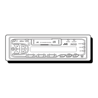
The KS-F171 is designed for ease of use within a vehicle environment. The detachable control panel enhances security by allowing users to remove the front panel when leaving the vehicle, deterring theft. The basic operation involves selecting between AM/FM radio and cassette playback. Volume, bass, treble, fader, loudness, Dolby NR, and sound cruise settings are adjustable to customize the audio experience.
Maintenance Features
The service manual provides detailed instructions for disassembly, adjustment, and troubleshooting, making the KS-F171 serviceable.
Disassembly Method:
The manual outlines a step-by-step process for disassembling the unit, starting from the front panel and progressing to internal components. Key steps include:
- Removing the front panel assembly.
- Removing the bottom cover.
- Removing the front chassis.
- Removing the heat sink.
- Removing the rear panel.
- Removing the main board.
- Removing the cassette mechanism assembly.
- Removing the head amplifier board.
- Removing the relay board.
- Removing the mecha bracket.
- Removing the switch (LCD & key) board.
- Disassembly of the cassette mechanism assembly, including:
- Direction switch board.
- FF / REW lever assembly.
- Playback head.
- Pinch-roller (R) and (F) assembly.
- Cassette hanger / cassette holder.
- Reel disc assembly.
- Motor assembly.
- Flywheel (BF) and (BR) assembly.
- Reel base assembly.
- Mute switch board.
- Power switch.
Adjustment Method:
The manual details various adjustments required for optimal performance, including:
- Head Azimuth Adjustment: Involves adjusting head height and azimuth using mirror tapes and test tapes (VT724, VT703, VT721) to ensure proper playback and phase difference within specified tolerances (e.g., phase difference within 45°, level difference between channels within 3dB for FWD/REV, and within 1.5dB for VT721).
- Tape Speed and Wow & Flutter Adjustment: Checking frequency counter and wow flutter meter readings (2940-3090 Hz, less than 0.35% JIS RMS) and adjusting the motor with a built-in volume resistor if out of specification.
- Playback Frequency Response Adjustment: Playing test tapes (VT724, VT739) and confirming output levels at specific frequencies (1kHz/8kHz, 125Hz/1kHz). Azimuth adjustment may be necessary if 8kHz is out of specification.
Test Instruments Required for Adjustment:
- Digital oscilloscope (100MHz).
- Frequency counter meter.
- Electric voltmeter.
- Wow & flutter meter.
- Test tapes (VT724, VT739, VT712, VT703, VT721).
- Torque gauge.
Car Audio Service Jig Information:
- The manual specifies the use of an extension cord (EXTKSRT002-6P) for connecting the mechanism assembly and main board during servicing, especially for checking operation after disassembly.
- A crucial caution is highlighted: "Be sure to attach a heat sink on the power amplifier IC of a main board when supplying the power. If voltage is applied without attaching the heat sink, the power amplifier IC will be destroyed by heat." This emphasizes the importance of proper thermal management during service.
The KS-F171 is designed with modular components, allowing for targeted repair and replacement of specific parts, such as the various boards and mechanical assemblies. The detailed pin functions for the major ICs provide essential information for circuit-level diagnostics and repair.