KS-FX742R
(No.49816)1-13
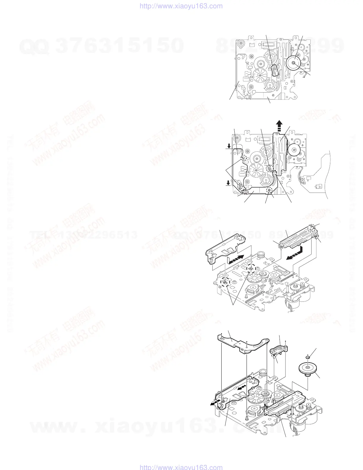
2.2.15 Removing the mode gear
(See Fig.28 and 31)
(1) Remove the polywasher on the bottom and pull out the
mode gear.
2.2.16 Removing the mode switch actuator
(See Fig.28, 29 and 31)
(1) Pull out the mode switch actuator at the bottom.
REFERENCE:
When reattaching the mode switch actuator to the main chas-
sis, make sure to set on the shaft and insert v into the slot w.
2.2.17 Removing the direction link / direction plate
(See Fig.29 to 31)
(1) Remove the polywasher attaching the direction link.
(2) Bring up the direction link to release the three joints x, y
and z at a time.
(3) Move the direction plate in the direction of the arrow to re-
lease the two joints a'.
REFERENCE:
When reattaching the direction plate, engage the two joints a'
and move in the direction of the arrow (Refer to Fig.30).
REFERENCE:
When reattaching the direction link, move the direction plate in
the direction of the arrow and engage the three joint x, y and
z at a time (Refer to Fig.31).
2.2.18 Removing the mode rack assembly
(See Fig.29 and 30)
(1) Move the mode rack assembly in the direction of the arrow
to release the two joints b' and the joint c'.
REFERENCE:
When reattaching, set the two b' Eon the bottom of the mode
rack assembly into the slots of the main chassis and move in
the direction of the arrow (See Fig.30).
Fig.28
Fig.29
Fig.30
Fig.31
Polywashe
Mode switch actuator
Mode gear
Direction plate
Direction link
Mode rack assembly
Slot w
Direction plate
Joints a'
Joint z
Direction link
Polywasher
Joint y
Joint x
Direction plate Mode rack assembly
Joint c'
Joint b'
Joint b'
Joints a'
Polywasher
Mode gea
Mode switch actuator
Direction link
Direction plate
Mode rack assembly
v
w
w
w
.
x
i
a
o
y
u
1
6
3
.
c
o
m
Q
Q
3
7
6
3
1
5
1
5
0
9
9
2
8
9
4
2
9
8
T
E
L
1
3
9
4
2
2
9
6
5
1
3
9
9
2
8
9
4
2
9
8
0
5
1
5
1
3
6
7
3
Q
Q
TEL 13942296513 QQ 376315150 892498299
TEL 13942296513 QQ 376315150 892498299
http://www.xiaoyu163.com
http://www.xiaoyu163.com
 Loading...