KS-FX742R
1-8 (No.49816)
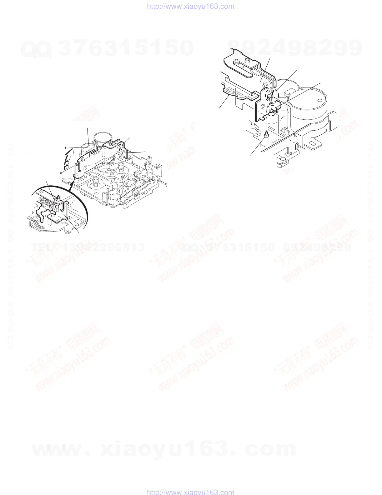
2.2.4 Removing the side bracket assembly
(See Fig.8 to 10)
(1) Remove the screw A attaching the side bracket assembly.
(2) Detach the front side of the side bracket assembly upward
and pull out forward to release the joint i and j in the rear.
CAUTION:
When reassembling, make sure that the boss k of the main
chassis is set in the notch of the load rack under the side
bracket assembly. Do not reattach the load rack on the boss k.
CAUTION:
After reattaching the side bracket assembly, confirm opera-
tion.
Fig.8
Fig.9
Fig.10
A
Side bracket assembly
Side bracket assembly
Joint i
Joint j
Joint i
Joint j
Side bracket assembly
Boss k
Load rack
w
w
w
.
x
i
a
o
y
u
1
6
3
.
c
o
m
Q
Q
3
7
6
3
1
5
1
5
0
9
9
2
8
9
4
2
9
8
T
E
L
1
3
9
4
2
2
9
6
5
1
3
9
9
2
8
9
4
2
9
8
0
5
1
5
1
3
6
7
3
Q
Q
TEL 13942296513 QQ 376315150 892498299
TEL 13942296513 QQ 376315150 892498299
http://www.xiaoyu163.com
http://www.xiaoyu163.com
 Loading...