MX-G50/MX-G56
1-33
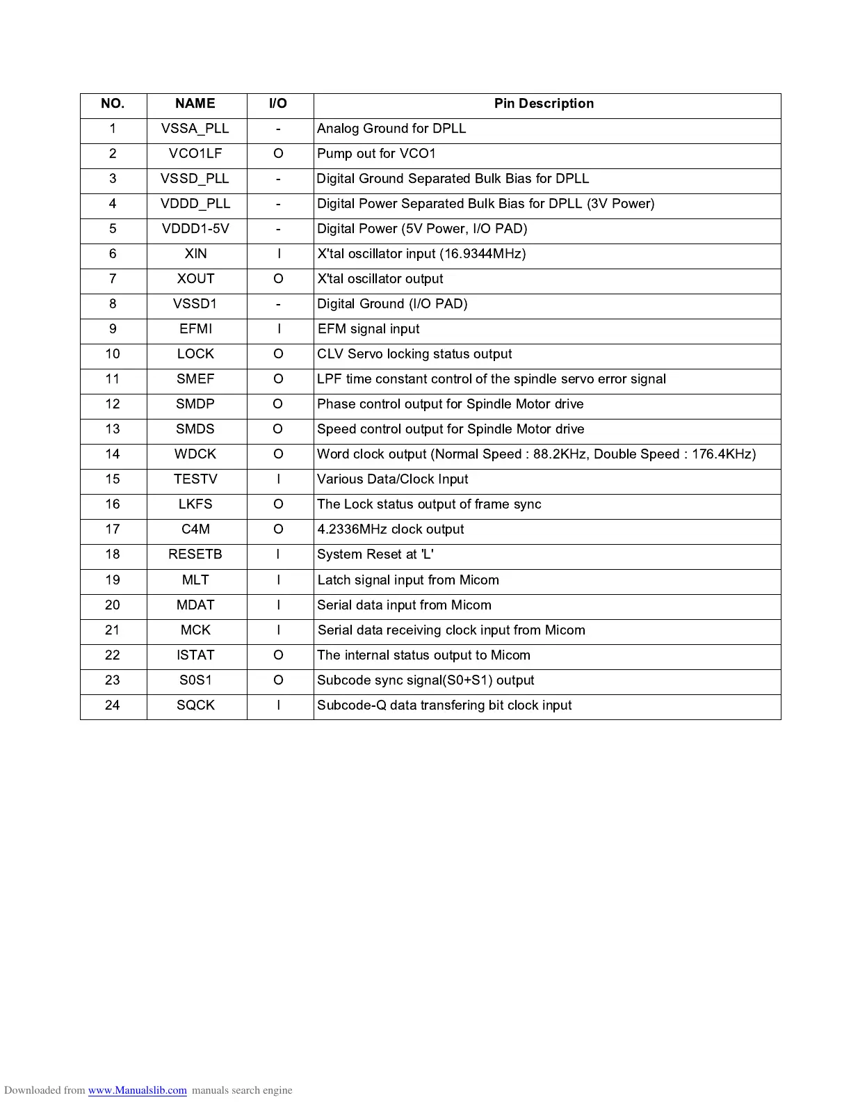
3. Pin function
(1/2)
NO. NAME I/O Pin Description
1 VSSA_PLL - Analog Ground for DPLL
2 VCO1LF O Pump out for VCO1
3 VSSD_PLL - Digital Ground Separated Bulk Bias for DPLL
4 VDDD_PLL - Digital Power Separated Bulk Bias for DPLL (3V Power)
5 VDDD1-5V - Digital Power (5V Power, I/O PAD)
6 XIN I X'tal oscillator input (16.9344MHz)
7 XOUT O X'tal oscillator output
8 VSSD1 - Digital Ground (I/O PAD)
9 EFMI I EFM signal input
10 LOCK O CLV Servo locking status output
11 SMEF O LPF time constant control of the spindle servo error signal
12 SMDP O Phase control output for Spindle Motor drive
13 SMDS O Speed control output for Spindle Motor drive
14 WDCK O Word clock output (Normal Speed : 88.2KHz, Double Speed : 176.4KHz)
15 TESTV I Various Data/Clock Input
16 LKFS O The Lock status output of frame sync
17 C4M O 4.2336MHz clock output
18 RESETB I System Reset at 'L'
19 MLT I Latch signal input from Micom
20 MDAT I Serial data input from Micom
21 MCK I Serial data receiving clock input from Micom
22 ISTAT O The internal status output to Micom
23 S0S1 O Subcode sync signal(S0+S1) output
24 SQCK I Subcode-Q data transfering bit clock input