MX-G50/MX-G56
1-10
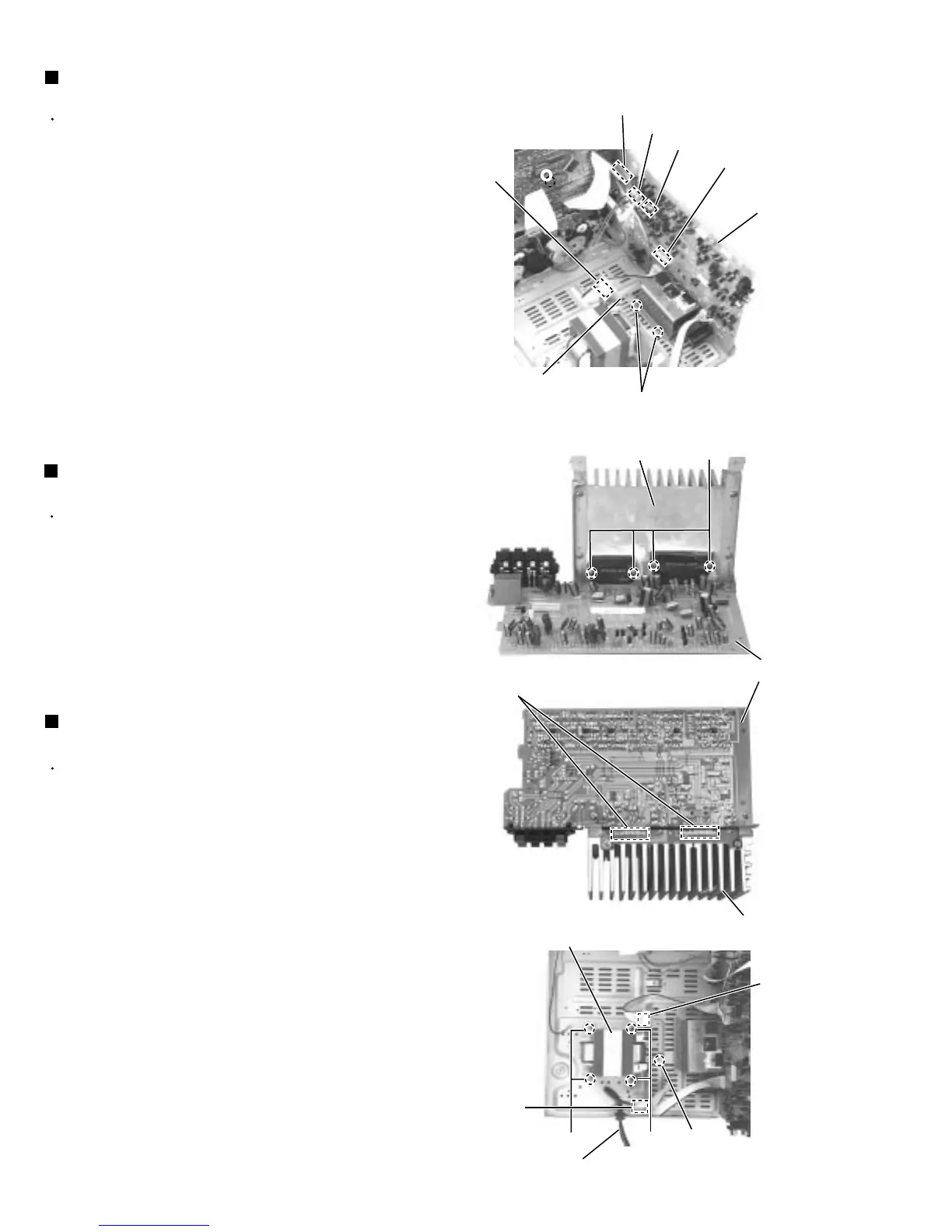
Prior to performing the following procedure, remove
the metal cover CD changer unit and heat sink &
AMP board.
Remove the four screws P attaching the power ICs
to the heat sink.
Unsolder the power ICs solder point.
1.
2.
Removing the power ICs
(See Fig.19 and 20)
Prior to performing the following procedure, remove
the metal cover, CD changer unit, heat sink & AMP
board tuner pack and rear cover.
Disconnect the card wire from connector FCW3 and
the harness from connector JCW1, JCW2 and
HCW3 on the main board.
Disconnect the harness from connector PCW1 on
the power transformer board.
Remove the screw G attaching the main board
holder. (See Fig.12)
Remove the two screws N attaching the heat sink
and bottom chassis.
1.
2.
3.
4.
Removing the main Board
(See Fig. 18)
Prior to performing the following procedure, remove
the metal cover, heat sink & AMP board, tuner pack
and rear cover.
Disconnect the power cord from connector RCW2 of
the power transformer board.
Disconnect the harness from connector PCW1 of the
power transformer board.
Remove the four screws R attaching the power
transformer and the screw S attaching the earth
terminal.
1.
2.
3.
Removing the power transformer
(See Fig .21)
Fig.21
Fig.20
Fig.19
Fig.18
Transformer board
N
R
R
S
P
Heat sink
AMP board
FCW3
JCW2
JCW1
HCW3
PCW1
Heat sink
Power cord
Power transformer
Power ICs solder point
Main board
RCW2
PCW1
 Loading...