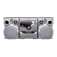
(No.MB550)1-9
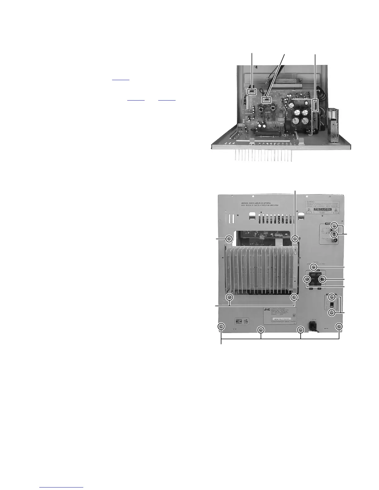
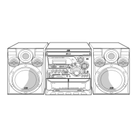
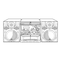
3.1.6 Removing the tuner pack
(See Fig.11)
(1) Remove the two screws J attaching the tuner pack.
3.1.7 Removing the amp board
(See Fig.10, 11)
(1) Disconnect the connector wire from the front board con-
nected to the connector CN202
of the amp board. (See
Fig.10)
(2) Disconnect the connector wires from the power transform-
er connected to the connector CN902
and CN903 of the
amp board. (See Fig.10)
(3) Remove the four screws K attaching the amp board. (See
Fig.11)
(4) Remove the three screws L attaching the amp board. (See
Fig.11)
3.1.8 Removing the voltage selector board
(See Fig.11)
(1) Remove the two screws M attaching the voltage selector
board.
3.1.9 Removing the rear panel
(See Fig.11)
(1) Remove the four screws N attaching the rear panel.
Fig.10
Fig.11
CN202 CN903CN902
K
K
K
L
L
L
M
N
J