1-10 (No.MB711<Rev.002>)
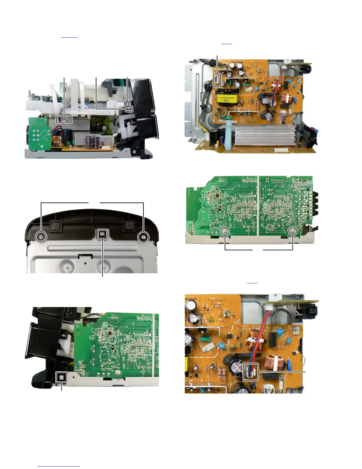
(2) Disconnect the connector wire from USB board connected
to connector CN801 of the Connection board. (See Fig.8)
(3) Remove the two screws K attaching the both side of the
DVD mechanism. (See Fig.8)
(4) Disengaged two hooks b engaged both side of the DVD
mechanism, (See Fig.8)
Fig.8
3.1.5 Removing the Front panel (See Fig.9, 10)
(1) Remove the two screws L attaching the Front panel.
(See Fig.9)
(2) Disengage one hook c engaged Front panel. (See Fig.9)
Fig.9
(3) Disengage two hooks d engaged both side of the Front
panel. (See Fig.10)
Fig.10
3.1.6 Removing the Amp board (See Fig.11, 12)
(1) Disconnect the connector wire from Amp board connected
to connector CN2
of the Power board. (See Fig.11)
Fig.11
(2) Remove the two screws M attaching the Amp board.
(See Fig.12)
Fig.12
3.1.7 Removing the Voltage selector board (See fig.13, 14)
(1) Disconnect the connector wire from Voltage selector board
connected to connector CN4
of the Power board.
(See Fig.13)
Fig.13
Khook bCN801
hook c
L
hook d
CN2
M
CN4
 Loading...