(No.MB711<Rev.002>)1-11
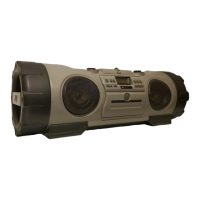
(2) Remove the one screw N attaching the Voltage selector
board. (See Fig.14)
Fig.14
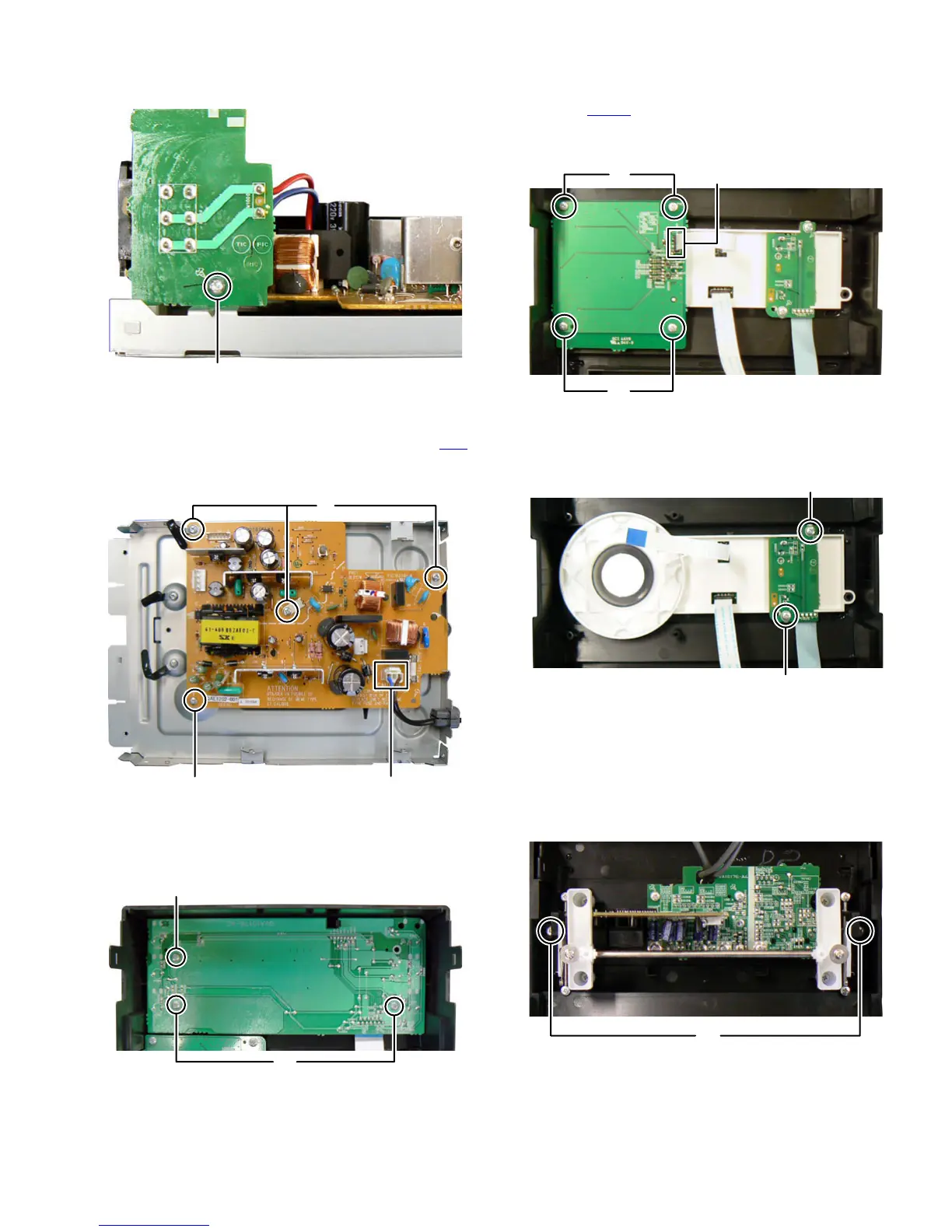
3.1.8 Removing the Power board (See Fig.15)
(1) Disconnect the Power cord connected to connector CN1
of
the Power board.
(2) Remove the four screws P attaching the Power board.
Fig.15
3.1.9 Removing the FL board (See Fig.16)
(1) Remove the three screws Q attaching the FL board.
Fig.16
3.1.10 Removing the Touch sensor board (See Fig.17, 18)
(1) Disconnect card wire from LED board connected to con-
nector CN920
of the Volume board. (See Fig.17)
(2) Remove the four screws R attaching the Volume board.
(See Fig.17)
Fig.17
(3) Remove the two screws S attaching the Touch sensor
board. (See Fig.18)
Fig.18
CAUTION:
The touch sensor board sticks to a front lens.
3.1.11 Removing the Mic board and USB board (See Fig.19,
20 and 21)
(1) Remove the two screws T attaching the Slide door.
(See Fig.19)
Fig.19
N
P
P
CN1
Q
Q
R
R
CN920
S
S
T
 Loading...