1-8 (No.MB711<Rev.002>)
SECTION 3
DISASSEMBLY
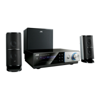
3.1 Main body (Used figure are NX-D7)
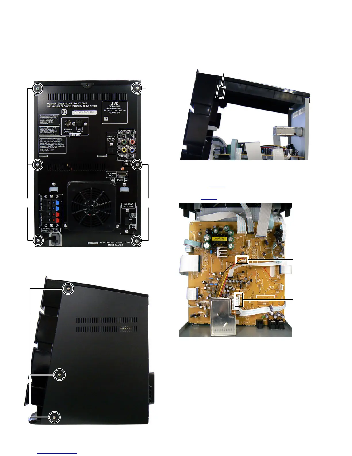
3.1.1 Removing the Top cover (See Fig.1, 2 and 3)
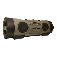
(1) Remove the five screws A and one screw B attaching the
Side panel. (See Fig.1)
Fig.1
(2) Remove the six screws C attaching the both side of the
Side panel and then side to backward to remove the Side
panel. (See Fig.2)
Fig.2
(3) Disengage two hooks a engaged both side of the Top cov-
er. (See Fig.3)
Fig.3
3.1.2 Removing the Rear panel (See Fig.4, 5)
(1) Disconnect the card wire from Tuner pack connected to
connector CN306
of the Main board. (See Fig.4)
(2) Disconnect the connector wire from FAN connected to con-
nector CN303 of the Main board. (See Fig.4)
Fig.4
A
B
C
hook a
CN306
CN303
 Loading...