(No.MB269)1-5
SECTION 3
DISASSEMBLY
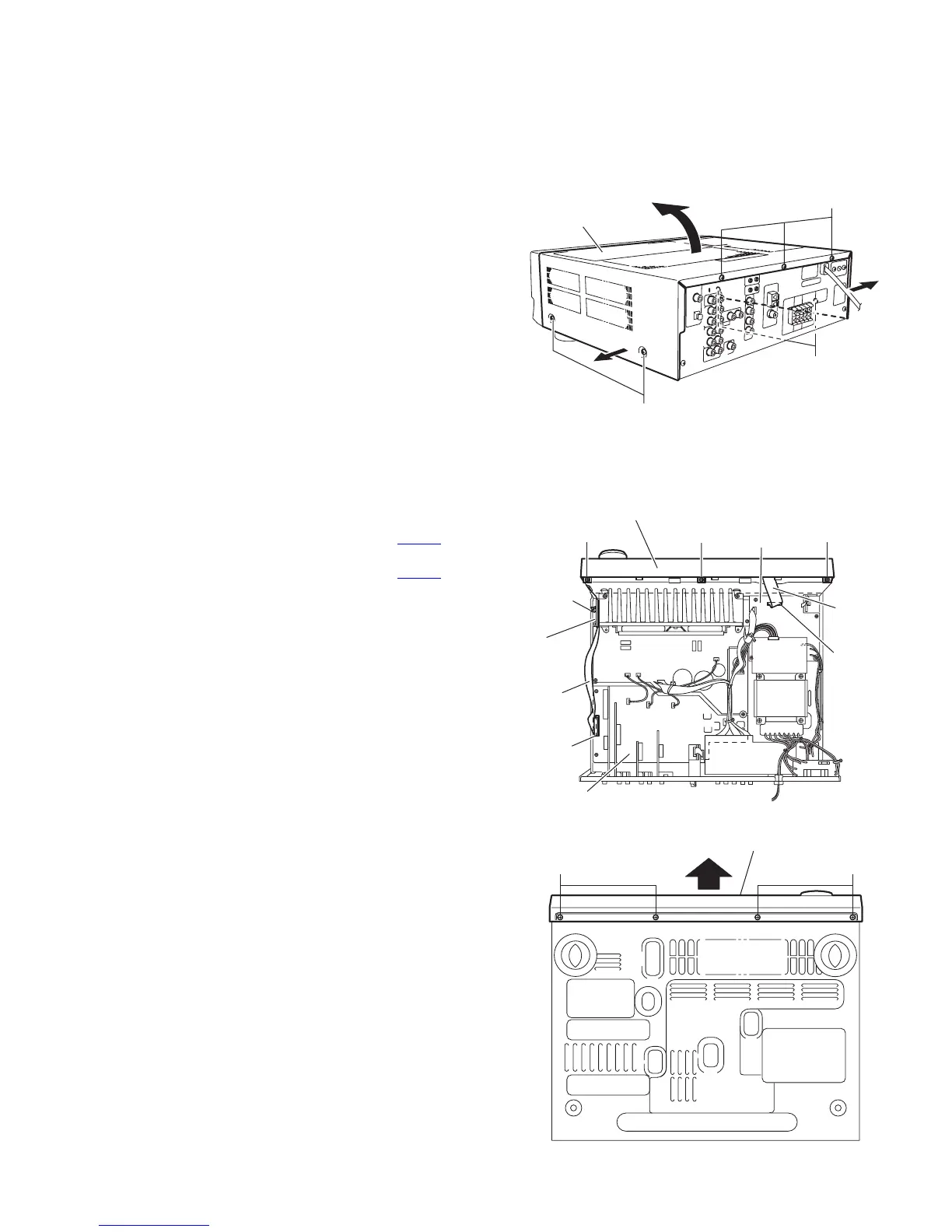
3.1 Removing the top cover
(See Fig.1)
(1) From the right and left sides of the main body, remove the
four screws A attaching the top cover.
(2) From the back side of the main body, remove the three
screws B attaching the top cover.
(3) Remove the top cover in the direction of the arrow 2 while
extending the lower sections of the top cover in the direc-
tion of the arrow 1.
Fig.1
3.2 Removing the front panel assembly
(See Figs.2 and 3)
• Prior to performing the following procedures, remove the top
cover.
(1) Disconnect the card wire from the connector CN402
on the
front board. (See Fig.2.)
(2) Disconnect the card wire from the connector CN201
on the
main board. (See Fig.2.)
(3) Remove the tie band and wire protection board fixing the
card wire. (See Fig.2.)
(4) Remove the three screws C attaching the front panel as-
sembly. (See Fig.2.)
(5) From the bottom side of the main body, remove the four
screws D attaching the front panel assembly. (See Fig.3.)
(6) Remove the front panel assembly in the direction of the ar-
row. (See Fig.3.)
Fig.2
Fig.3
B
A
A
2
1
1
Top cover
C
Front panel assembly
Card wire
CN201
Main board
Tie band
Wire
protection
board
Card wire
CN402
Front board
C
C
DD
Front panel assembly
 Loading...