RX-7010RBK/RX-7012RSL
1-4
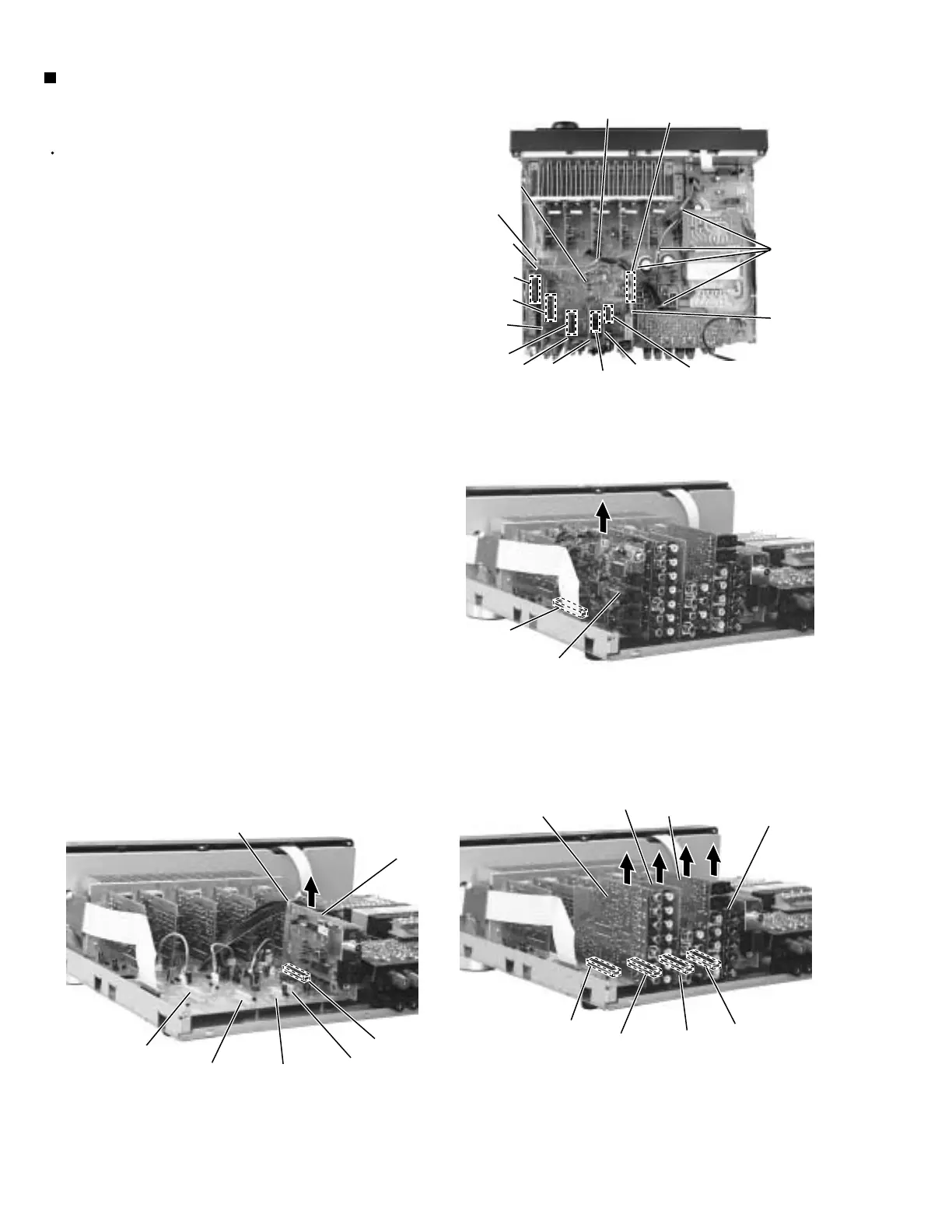
Prior to performing the following procedure, remove
the top cover and the rear panel.
Cut off the tie band fixing the harness.
Disconnect the DSP board from connector CN481 on
the audio board.
Disconnect the audio input board, DVD board Video
board and the S video board from connector CN421,
CN431,CN441 and CN461 on the audio board.
Disconnect the tuner board from connector CN411
and CN412 on the audio board.
1.
2.
3.
4.
Removing each board connected to the
rear side of the audio board
(See Fig.5 to 8)
Fig.5
Fig.6
Fig.7
Fig.8
CN411
CN412
Tie band
DSP
board
DVD
board
Video
board
Tuner
board
Audio
input
board
DSP board
CN481
CN441
CN431
CN421
CN481
CN421
CN431
CN441
CN411
CN412
Tie band
CN421
CN431
CN441
Audio
input
board
DVD
board
Video
board
Tuner
board
Audio
board
CN461
S Video
board
CN461
S Video
board
CN461
Tie band
Tie band
 Loading...