RX-7010RBK/RX-7012RSL
1-5
Prior to performing the following procedure, remove
the top cover and the rear panel.
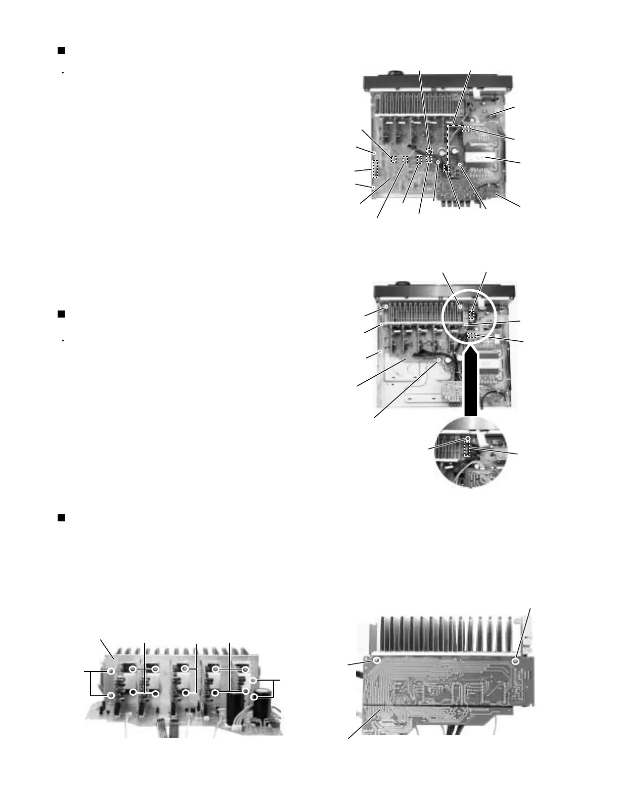
Removing the audio board (See Fig.9)
Disconnect the card wire from connector CN402 on
the audio board.
Disconnect the relay board from the audio board and
the power supply board. (CN291,CN491)
Disconnect the harness from connector CN473,
CN471, CN472, CN403 and CN385.
Remove the three screws G attaching the audio
board assembly.
Remove the screw H attaching the audio board
assembly.
1.
2.
3.
4.
5.
Remove the ten screws K and four screws L
attaching the heat sink.
Remove the two screws L' attaching the heat sink
from the rear side of main board.
1.
2.
Removing the Heat sink
(See Fig.11 to 12)
Prior to performing the following procedure, remove
the top cover, the rear panel and audio board.
Disconnect the harness from connector CN241 and
CN203 on the power supply board respectively.
Remove the four screws I and the two screws J
attaching the main board.
In case where the sub board is installed,detach it
after removing the connectors CN208,CN209 and
CN210 as well as the screw J'.
1.
2.
3.
Removing the main board (See Fig.10)
Fig.9
Fig.10
Fig.11
Fig.12
power
supply
board
Power / Fuse
board
Relay board
CN473
Audio board
Main board
rear side
Main
board
Heat sink
CN291
CN203
CN491
H
G
CN471
CN403
CN402
CN472
Power
transformer
G
G
CN241
I
I
I
I
J
J
L
L
K
K
K
L'
L'
J'
CN208
CN209
CN210
CN385
 Loading...