(No.MB170)1-11
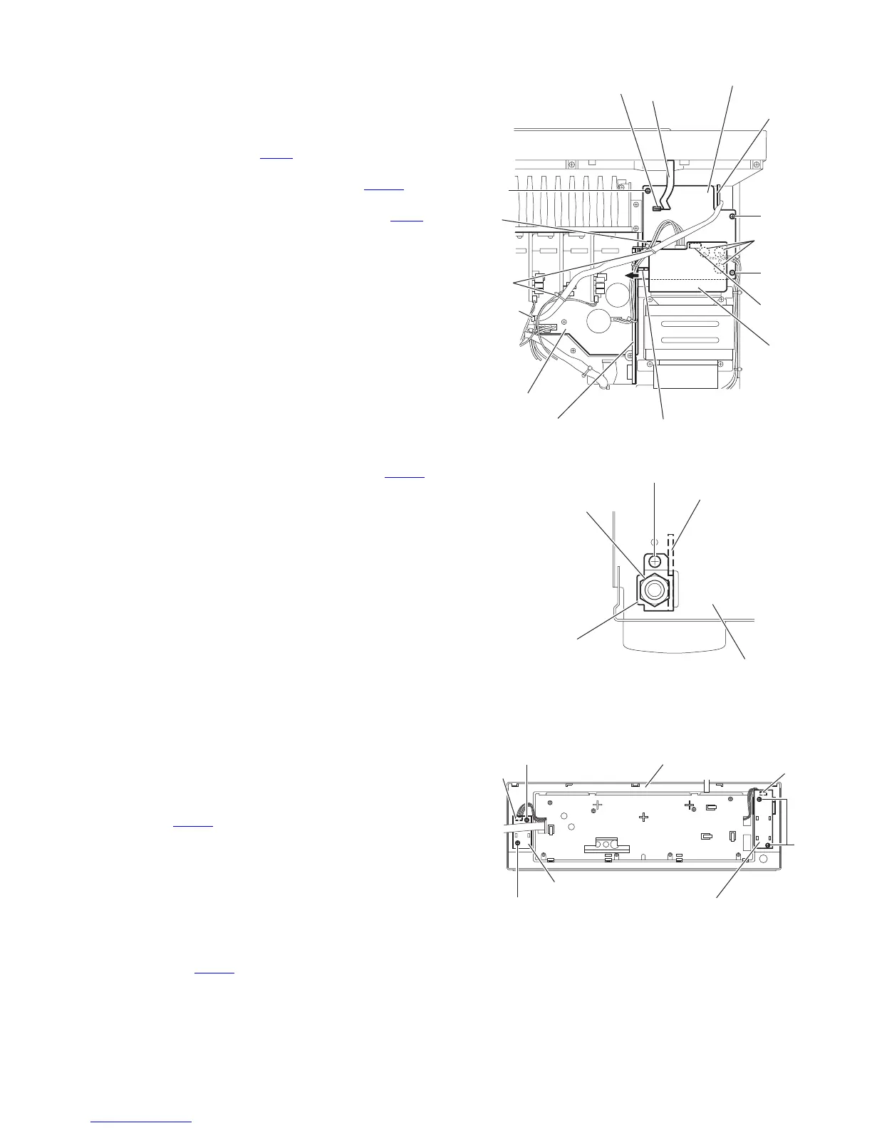
3.13 Removing the power supply board
(See Fig.14)
• Prior to performing the following procedures, remove the top
cover.
(1) From the top side of the main body, disconnect the parallel
wires from the connector CN55
on the power transformer
board 1.
(2) Disconnect the card wire from the connector CN402
on the
power supply board.
(3) Disconnect the relay board from the connector CN71
on
the power supply board.
(4) Remove the three screws U attaching the power supply
board.
(5) Remove the power supply board from the hook d of the
chassis base bracket in the direction of the arrow, take out
the power supply board.
(6) Turn over the power supply board, remove the solders from
the soldered sections e attaching the wires.
3.14 Removing the headphone jack board
(See Figs.14 and 15)
• Prior to performing the following procedures, remove the top
cover and front panel assembly.
(1) From the top side of the main body, remove the tie bands
attaching the parallel wire. (See Fig.14)
(2) Disconnect the parallel wire from the connector CN881
on
the main board. (See Fig.14)
(3) From the front side of the main body, remove the nut and
screw V attaching the headphone bracket to the front
bracket. (See Fig.15)
(4) Remove the three screws U attaching the power supply
board. (See Fig.14)
(5) Take out the headphone jack board from the inside of the
chassis base while lifting the power supply board.
Fig.14
Fig.15
3.15 Removing the switch board
(See Fig.16)
• Prior to performing the following procedures, remove the top
cover and front panel assembly.
(1) From the back side of the front panel assembly, remove the
two screws W attaching the switch board.
(2) Take out the switch board, disconnect the wire from the
connector CN432
on the switch board.
3.16 Removing the power switch board
(See Fig.16)
• Prior to performing the following procedures, remove the top
cover and front panel assembly.
(1) From the back side of the front panel assembly, remove the
two screws X attaching the power switch board.
(2) Take out the power switch board, disconnect the wire from
the connector CN430
on the power switch board.
Fig.16
CN55
Power
transforme
board 1
Hook d of the chassis base bracket
U
Relay board
CN402
Card wire
Power supply board
CN71
U
U
Soldered
sections e
Tie
bands
Headphone
jack board
Main board
CN881
Nut
Headphone jack board
Headphone bracket
Front bracket
V
CN432
W
W
Switch board
Front panel assembly
CN430
Power switch board
X
 Loading...