RX-7520VBK
1-6
Prior to performin
the followin
procedure, remove
the top cover and the rear panel
Removin
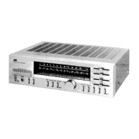
the audio board (See Fi
.10
Disconnect the card wire from connector
N4
2 on
th
io
o
r
Disconnect the rela
board from the audio board and
the power suppl
board. (CN291, CN491
Disconnect the harness from connector CN471
CN472
CN473
Remove the three screws G attachin
the audio
board assembl
Remove the screw H attachin
the audio board
assembl
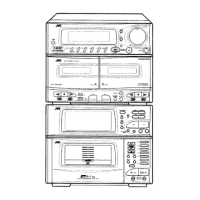
Removin
the Heat sin
(See Fi
.12 to 14
Prior to performin
the followin
procedure, remove
the top cover, the rear panel and audio board
Disconnect the harness from connector
N241 and
CN203 on the power suppl
board respectivel
Disconnect the harness from connector
N2
1 on
the power transformer board
Remove the four screws I and the two screws
attachin
the main board
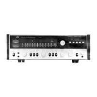
Removin
the main board (See Fi
.11
Prior to performin
the followin
procedure, remove
the top cover and main board
R
mov
th
two
r
w
attachin
the heat sink to
th
r
v
r
i
of m
in
o
r
Disconnect the for connectors with each amp. board,
n
r
mov
th
m
in
o
r
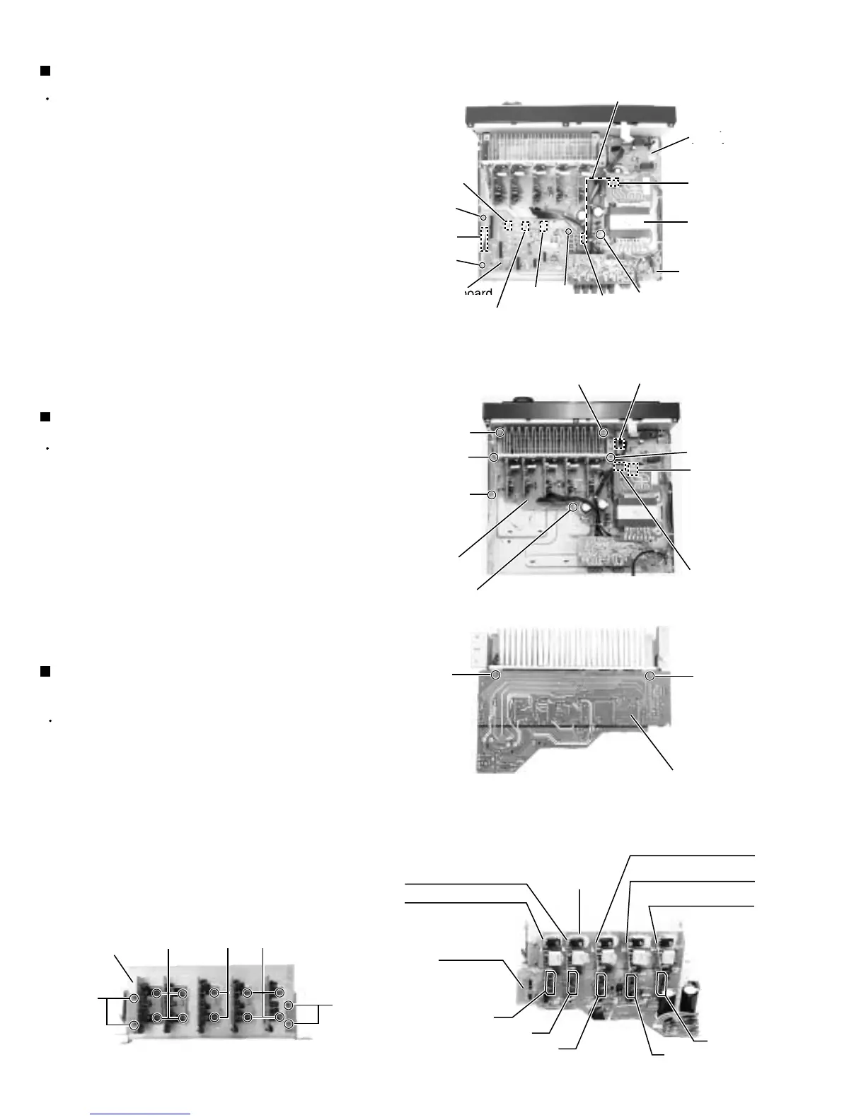
R
mov
th
fo
r
r
w
n
t
n
r
w
attachin
the heat sink
Fig.10
Fig.13
Fig.11
Fig.12
powe
supply
o
r
board
Power
Fus
o
r
Rela
board
N47
Main board
rear side
Main
o
r
Heat sink
N2
CN203
CN491
H
G
CN471
N4
CN472
Pow
r
tr
n
form
G
G
CN241
I
I
I
I
J
J
L
L
K
K
M
M
CN251
L
Fig.14
Main board
Rear Rch amp. boar
Front Lch amp. board
Front Rch amp. board
Center amp. board
ear
c
amp.
oar
Heat sink
CN802
CN801
CN302
CN301
CN901
 Loading...