RX-7520VBK
1-7
Prior to performin
the followin
procedure, remove
the top cover and the rear panel
Remove the screw
attachin
the power
fuse
o
r
Unsolder the power cord and other harnesses
connected to the power / fuse board
Removin
the power / fuse boar
(See Fi
.15
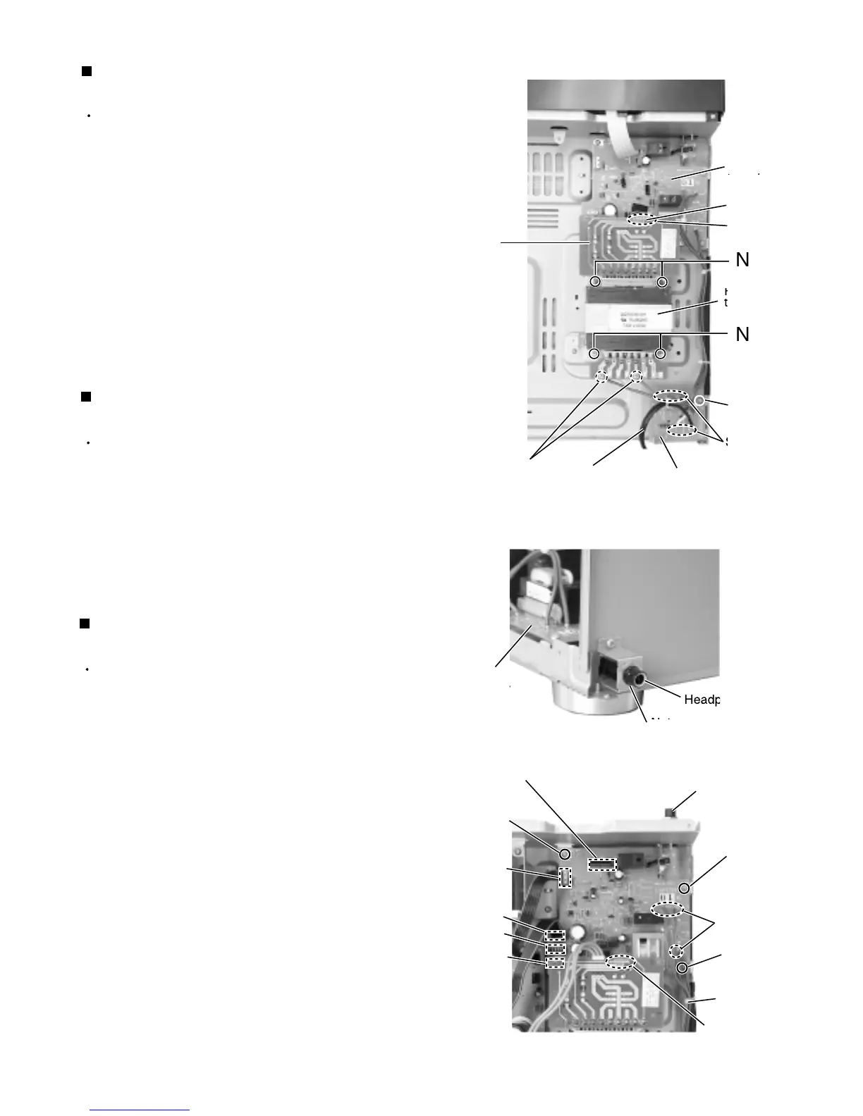
Prior to performin
the followin
procedures, remove
the top cover
Cut off the tie band fixin
the harness
Unsolder the two harnesses connected to the power
tr
n
form
r
nsolder the harness connected to the FW2
1 on
the power transformer board
Remove the four screws N attachin
the power
tr
n
form
r
Removin
the power transforme
(See Fi
.15
Prior to performin
the followin
procedure, remove
the top cover and the front panel
Remove the one nut attachin
the headphone jack of
the power suppl
board on the front side of the bod
Di
onn
t th
h
rn
onn
t
to
onn
tor
CN241, CN201, CN203, and CN291 on the power
supply board (If necessary, cut off the band fixin
the
harness on the side of the base chassis
Remove the three screws P attachin
the power
suppl
board and pull out the power suppl
board
from th
front
r
k
t
kw
r
nsolder the three harnesses connected to the
power suppl
board
Removin
the power supply board
(See Fi
.16 , 17
Fi
.1
Fi
.1
Fig.17
Pow
o
r
board
ow
r
r
n
form
N24
olde
point
olde
point
olde
Pow
r
or
Pow
r
suppl
o
r
hone
ack
Headphone
ac
Ti
n
Solder point
P
P
olde
point
CN201
N2
H
Pow
r
tr
n
form
o
r
FW2
N2
 Loading...